PN25

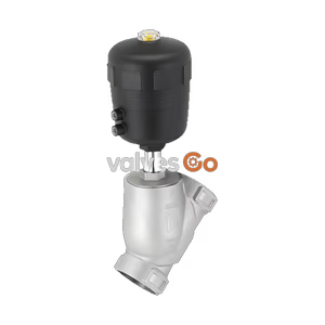
BURKERT 344484 (Type 2000) is a double-acting pneumatically operated 2/2-way angle seat valve with DN25 welded ends, CF3M stainless steel body, PA actuator, and PTFE seat seal for neutral and aggressive media.
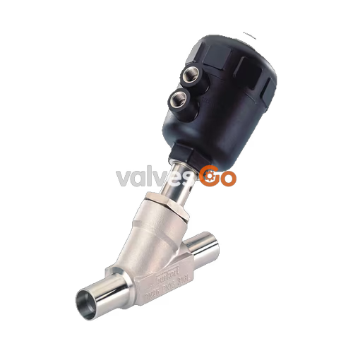
BURKERT 344484 (Type 2000) is an externally piloted 2/2-way angle seat valve designed for discrete process automation and fluid shut-off duties. The assembly consists of a pneumatically actuated polyamide (PA) piston actuator and an investment-cast stainless steel CF3M (316L) angle seat valve body. Process connection 1 is engineered as a welded connection conforming to ISO 4200, DIN EN ISO 1127, and DIN 11866 Series B, with a nominal diameter of DN 25, an outer pipe diameter of 33.7 mm, and a 2.0 mm wall thickness. Configured with double-acting Control Function I, the valve utilizes compressed air or neutral gas across two control air ports to actively drive the valve disc open and closed, eliminating spring dependency and providing defined actuation in both travel directions.
Operating with flow direction below the valve seat, BURKERT 344484 delivers a water flow coefficient (Kv) of 15 m³/h with an orifice seat size of 25 mm. The valve body accommodates working pressures from 0 to 16 bar(g) and fluid temperatures from -10 °C to +185 °C under nominal pressure classes PN 25 (DIN EN 1333) and Class 150 (DIN EN 1759). Tight shut-off is ensured by a virgin PTFE seat seal meeting leakage rate A in accordance with DIN EN 12266-1. Spindle sealing is achieved through a self-adjusting packing gland equipped with spring-compensated PTFE V-rings, protecting process integrity across liquid, gas, and steam duties.

BURKERT 344484 features an integrated construction comprising the actuator head, internal spindle transmission, and flow-diverting body. Closing and opening forces generated by the piston are transmitted directly to the swivel plate disc via a solid 1.4401/1.4404 stainless steel spindle. An integrated relief bore on the actuator neck provides atmospheric venting between the actuator chamber and the fluid packing gland, serving as an external indicator port in the event of packing wear.
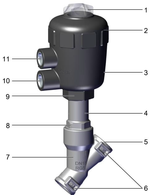
| Item | Description | Item | Description |
|---|---|---|---|
| 1 | Transparent cover with visual position indicator | 7 | Valve body (CF3M stainless steel) |
| 2 | Actuator cover (PA) | 8 | Body connection mechanism with wrench flats |
| 3 | Actuator housing (PA) | 9 | Wiper seal and intermediate packing |
| 4 | Atmospheric relief/bleed bore | 10 | Lower control air port (G 1/4) |
| 5 | Welded pipe connection (ISO 4200 / DIN 11866 B) | 11 | Upper control air port (G 1/4) |
| 6 | Flow direction arrow mark |
Control Function I (SFI / DA) operates without an internal return spring. Both switching operations require positive pneumatic pressure:
Operating Safety under Control Function I
Because Control Function I does not have a spring-driven mechanical fail-safe position, an unexpected loss of supply air causes the valve to remain in its last travel state. Prior to servicing or system restart, depressurize the pipe lines, restore pilot air pressure to establish a controlled state, and then admit process fluid.
BURKERT 344484 is configured exclusively for flow entering below the seat. In this arrangement, line medium enters beneath the swivel plate so that system line pressure assists the pneumatic opening stroke. Flowing against the seat face prevents water hammer surges when handling liquids, neutral media, or condensable vapors.
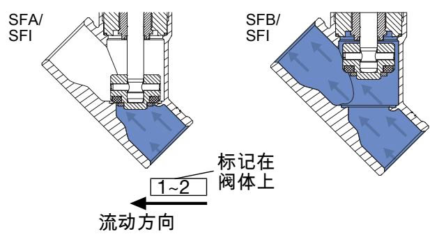
Restriction Against Flow Above Seat for Liquids
Valves directing flow above the seat must never be used with liquid media due to hydraulic shock waves (water hammer) that burst piping and valve housings. Flow below the seat is the specified orientation for all liquid, steam, and neutral gas duties on article 344484.
All wetted parts and structural casing elements are manufactured from corrosion-resistant materials certified for industrial and sanitary utilities, supporting CIP and SIP chemical cleaning.
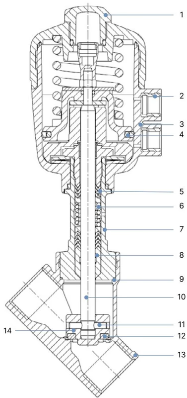
| No. | Component | Material Formulation |
|---|---|---|
| 1 | Transparent Position Cover | Polycarbonate (PC) |
| 2 | Pilot Air Ports | Stainless steel 1.4305 |
| 3 | Actuator Housing & Cover | Polyamide (PA) |
| 4 | Piston Seal | Nitrile butadiene rubber (NBR) |
| 5 | Spindle Packing Gland | Filled PTFE V-rings with spring compensation (1.4310 spring) |
| 6 | Tube Insert | Stainless steel CF3M |
| 7 | Wiper Ring | Filled PTFE |
| 8 | Body Seal Ring | Graphite (optional PTFE) |
| 9 | Valve Spindle | Stainless steel 1.4401 / 1.4404 (316 / 316L) |
| 10 | Disc Retention Pin | Stainless steel 1.4401 / 1.4404 |
| 11 | Seat Seal Disc | Polytetrafluoroethylene (PTFE) |
| 12 | Valve Body | Cast stainless steel CF3M (equivalent to AISI 316L) |
| 13 | Swivel Plate (Disc Holder) | Stainless steel CF3M / 1.4404 / 1.4401 |
BURKERT 344484 operates within specified fluidic and thermodynamic boundaries defined by the combination of a polyamide actuator and a stainless steel body.
| Parameter | Technical Value |
|---|---|
| Medium Compatibility | Water, alcohols, oils, fuels, hydraulic fluids, saline solutions, lyes, organic solvents, steam, neutral gases |
| Operating Pressure Range | 0 to 16 bar(g) (vacuum down to -0.9 bar(g) available on vacuum variants) |
| Nominal Pressure Class | PN 25 (DIN EN 1333) / Class 150 (ASME B16.5 / B16.34) |
| Pilot Pressure Range | 2.0 to 10.0 bar(g) |
| Pilot Air Connection | G 1/4 female thread |
| Medium Temperature Range | -10 °C to +185 °C |
| Ambient Temperature Range | -10 °C to +40 °C (derating applies at elevated medium temperatures) |
| Storage Temperature | -20 °C to +65 °C |
| Environmental Protection | IP67 (EN 60529 / IEC 60529) |
| Acoustic Noise Emission | < 70 dB(A) under standardized testing |
| Maximum Fluid Viscosity | 600 mm²/s |
The maximum permissible working pressure of the CF3M stainless steel body decreases at elevated temperatures in accordance with DIN EN 12516-1 and ASME B16.34:
| Medium Temperature (°C) | DIN EN 12516-1 PN25 Maximum Pressure (bar) | ASME B16.34 Class 150 Maximum Pressure (bar) |
|---|---|---|
| -10 to +38 / +50 | 25.0 | 19.0 |
| 100 | 24.5 | 16.2 |
| 150 | 22.4 | 14.8 |
| 185 / 200 | 20.3 | 13.7 |
| 230 | 19.0 | 12.7 |
Actuator Thermal Limits
For PA actuators (size 50 / D), when medium temperatures reach the maximum rating of +185 °C, ambient temperature must not exceed +40 °C. If ambient temperature reaches +60 °C, the continuous medium temperature must be maintained below +140 °C.
Process port 1 features orbital butt-weld ends conforming to DIN EN ISO 1127, ISO 4200, and DIN 11866 Series B for DN 25 process piping.
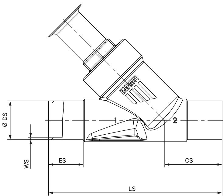
| Size | Pipe OD ø DS (mm) | Wall Thickness WS (mm) | Inner Diameter (mm) | Face-to-Face Length LS (mm) | End Length ES (mm) | Centerline Height CS (mm) |
|---|---|---|---|---|---|---|
| DN 25 | 33.7 | 2.0 | 29.7 | 130 | 26 | 43 |
| Dimension Code | Metric Value (mm) | Dimension Reference Description |
|---|---|---|
| ø A | 64 | Outer diameter of PA actuator cover/casing |
| B / H | 152 | Centerline to top of actuator body |
| K / M | 136 | Centerline to lower pilot port center |
| P | G 1/4 | Pilot air female threaded port size |
| BS / HS | 223 | Total clearance height from bottom of valve body to indicator dome |
Installation can occur in any mounting orientation, though an upright actuator position is recommended to reduce particulate settling in the packing gland area.
Welded Connection Procedure
When installing valves with welded connections, the actuator assembly must be detached from the valve body before welding. Thermal radiation from orbital or manual welding will destroy the internal PTFE seat seal, spindle packing V-rings, and actuator polymer housing.
Follow these sequential mechanical instructions:
Control air supply lines can be routed cleanly by rotating the actuator head 360° relative to the body.
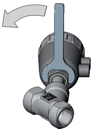
Use clean, dry instrument air or neutral gas meeting process standards. Hoses must withstand operating pressures up to 10 bar and surrounding thermal conditions.
Commissioning Protocol
To achieve controlled, water-hammer-free initial operation, apply pilot air pressure to confirm actuator travel before introducing pressurized pipeline media. Verify that line pressure never exceeds 16 bar and that medium temperature stays within the limits of the rating plate.
The actuator mechanism is maintenance-free under normal operating conditions. Regular maintenance schedules should inspect sealing interfaces for process leakage.
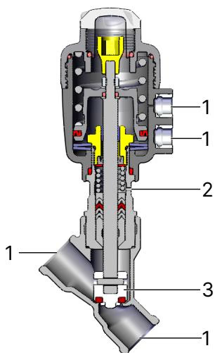
| Inspection Point | Visual Condition | Corrective Maintenance Action |
|---|---|---|
| Media Connection (1) | Fluid seepage at weld joints | Repair weld joint or pipe alignment |
| Relief Bore (2) | Medium or pilot air weeping | Replace spindle packing gland kit or replace actuator |
| Swivel Disc (3) | Scratches, grooves, or seat bypass | Replace valve set (swivel plate and PTFE seal) |
| Body Joint Seal | External seepage above hexagon | Replace graphite body seal ring |
| Malfunction | Probable Cause | Corrective Action |
|---|---|---|
| Actuator fails to stroke | Pilot lines reversed | Connect opening pilot line to lower port; closing line to upper port |
| Pilot pressure below minimum limit | Increase control air pressure to minimum 2 to 4 bar | |
| Line pressure exceeds 16 bar limit | Regulate system operating pressure within rating limits | |
| Internal seat leakage | Debris trapped between plug and seat | Flush pipeline; install upstream strainer (< 1 mm mesh) |
| PTFE seat seal worn or mechanically cut | Install replacement valve set (swivel plate disc) | |
| Reverse flow orientation | Ensure pipe flow aligns with valve body arrow (flow under seat) | |
| Leakage at relief bore | Spindle V-ring packing gland worn | Install replacement packing gland seal kit using assembly tools |
Only genuine Bürkert spare kits should be employed to preserve type approvals and pressure integrity.
Explore similar products in our catalog