


Up to 99.8% Efficiency

BURKERT 346328 (Type 3361) is an electromotive 2-way globe control valve with DN 25 ASME BPE clamp connections, 24 V DC AG2 actuator, PTFE seat seal, and büS/EtherNet/IP communication.
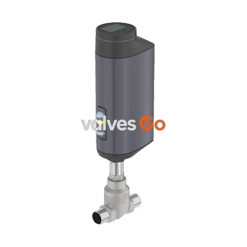
BURKERT 346328 (Type 3361) is an electromotive 2-way globe control valve engineered for demanding continuous control tasks in hygienic and industrial fluid processes. The unit integrates a brushless DC electric linear drive with a ball screw mechanism to position a stainless steel control cone with high repeatability. Operating at a linear speed of 6 mm/s with an AG2 actuator nominal force of 1300 N, the valve reacts to dynamic control setpoints with minimal dead time and maintains an operating dead band of ±0.1%. Fluid pressure variations or system pressure shocks do not transfer to the drive or disrupt spindle position.
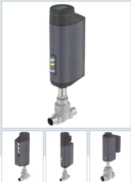
This specific configuration incorporates a DN 25 (NPS 1) cast stainless steel CF3M valve body equipped with ASME BPE clamp connections (pipe dimensions 25.4 x 1.65 mm, clamp flange diameter 50.5 mm). Flow enters below the seat (flow direction 2 to 1). Sealing at the seat is executed via a replaceable PTFE soft seal, delivering bubble-tight Class VI shut-off across an operating pressure span from 0 to 25 bar(g). The internal orifice features a 20 mm seat diameter, providing a rated Kv value of 7.1 m³/h (Cv 8.3 gpm) and an equal percentage 50:1 theoretical rangeability. The valve includes an integrated EtherNet/IP industrial Ethernet gateway and a rugged local display interface with operational keys.
INFO
BURKERT 346328 is configured with the standard control function: static position blocking without electrical energy storage. Upon interruption of the 24 V DC electrical power supply, the actuator holds its current physical stroke position.
| Parameter | Specification |
|---|---|
| Article Number | 346328 |
| Valve Type | 3361 |
| Design | Electromotive 2-way globe control valve |
| Nominal Diameter | DN 25 (NPS 1) |
| Port Connection | Clamp ASME BPE / BS4825-3 (Tube: 25.4 x 1.65 mm, Cl: 50.5 mm) |
| Actuator Size / Nominal Force | AG2 (1300 N) |
| Operating Voltage | 24 V DC ±10% (max. residual ripple 10%) |
| Operating Current | Max. 3 A (load dependent) |
| Standby Power Consumption | 2 to 5 W |
| Operating Pressure Range | 0 to 25 bar(g) |
| Nominal Pressure Class | PN 25 (DIN EN 1333) / Class 150 (DIN EN 1759) |
| Medium Temperature Range | -10 °C to +130 °C |
| Permissible Ambient Temperature | -25 °C to +65 °C (subject to temperature derating) |
| Seat Orifice Size | 20 mm (3/4") |
| Flow Coefficient | Kv = 7.1 m³/h (Cv = 8.3 gpm) |
| Flow Characteristic | Equal percentage (theoretical rangeability 50:1) |
| Seat Leakage Class | Class VI (DIN EN 60534-4) |
| Actuator Travel Speed | 6 mm/s |
| Typical Closing Time | 3.3 s |
| Dead Band | ±0.1% |
| Flow Direction | Against closing direction (flow below seat, 2 → 1) |
| Safety Setting on Power Loss | Blocked in last static position |
| Actuator Weight | Max. 5.5 kg (AG2 actuator) |
| Ingress Protection Rating | IP65 / IP67 (DIN EN 60529), NEMA 4X |
| Protection Class | Class III (DIN EN 61140) |
| Conformity & Approvals | EC Regulation 1935/2004 (food contact materials) |
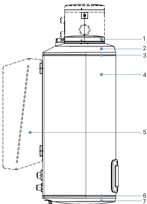
| Item | Component | Material |
|---|---|---|
| 1 | Display housing / Gateway housing | PPS (standard) |
| 2 | Actuator cover | PPS |
| 3, 6 | O-ring seals | EPDM |
| 4 | Actuator housing | Powder-coated aluminium |
| 7 | Actuator base | PPS |
| — | Spindle | Stainless steel 1.4401 (316) / 1.4404 (316L) |
| — | Spindle seal | PTFE V-seals (filled) with spring compensation |
| — | Spindle guide | Stainless steel 1.4404 (316L) |
| — | Packing gland tube | Stainless steel 1.4401 (316) |
| — | Valve body seal | Graphite or PTFE |
| — | Seat seal | PTFE seal washer (Leakage Class VI) |
| — | Control cone | Stainless steel 1.4571 |
| — | Valve seat | Stainless steel 1.4571 |
| — | Valve seat O-ring | EPDM or PTFE |
| — | Valve body | Cast stainless steel CF3M |
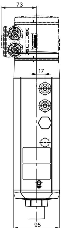
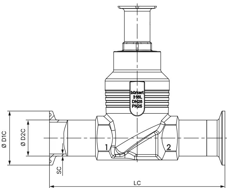
For nominal diameter DN 25 (NPS 1), the AG2 actuator equipped with the integrated industrial fieldbus gateway corresponds to the following vertical installation dimensions:
| Parameter | Value (DN 25 / NPS 1) |
|---|---|
| Connection Standard | ASME BPE / DIN 32676 Series C (Pipe: ASME BPE / DIN 11866 Series C) |
| Face-to-Face Body Length (LC) | 126 mm |
| Internal Pipe Diameter (∅ D2 C) | 25.4 mm |
| Clamp Flange Outer Diameter (∅ D1 C) | 50.5 mm |
| Pipe Wall Thickness (SC) | 1.65 mm |
BURKERT 346328 utilizes dedicated external M12 circular plug connectors located on the AG2 actuator base and gateway module.
| Connector | Coding | Description |
|---|---|---|
| X3 | M12 circular plug, 5-pin, A-coded | Operating voltage 24 V DC and büS/CANopen communication |
| X7 (Port 1 & 2) | M12 circular socket, 4-pin, D-coded | Industrial Ethernet fieldbus connection (integrated 2-port Ethernet switch) |
| Pin | Signal Assignment |
|---|---|
| 1 | CAN Shield / Functional shield |
| 2 | Operating voltage 24 V DC ±10% |
| 3 | GND / CAN_GND |
| 4 | CAN_H |
| 5 | CAN_L |
| Pin | Signal Assignment |
|---|---|
| 1 | Transmit Data + (TX+) |
| 2 | Receive Data + (RX+) |
| 3 | Transmit Data - (TX-) |
| 4 | Receive Data - (RX-) |
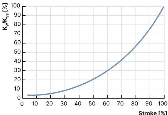
The Type 3361 globe control valve follows an equal-percentage flow characteristic according to DIN EN 60534-2-4. For seat size 20 mm, the theoretical rangeability is 50:1. The measured flow coefficients across intermediate spindle strokes are detailed below.
| Parameter | Performance Value |
|---|---|
| Nominal Port Diameter | DN 25 (NPS 1) |
| Seat Orifice Size | 20 mm |
| Actuator Drive Force | 1300 N |
| Max. Operating Pressure (PTFE Seal) | 25 bar(g) (Leakage Class VI) |
| Theoretical Rangeability | 50:1 |
| Kv at 5% Stroke | 0.20 m³/h |
| Kv at 10% Stroke | 0.25 m³/h |
| Kv at 20% Stroke | 0.31 m³/h |
| Kv at 30% Stroke | 0.47 m³/h |
| Kv at 40% Stroke | 0.70 m³/h |
| Kv at 50% Stroke | 1.1 m³/h |
| Kv at 60% Stroke | 1.6 m³/h |
| Kv at 70% Stroke | 2.5 m³/h |
| Kv at 80% Stroke | 3.8 m³/h |
| Kv at 90% Stroke | 5.4 m³/h |
| Rated Flow Coefficient Kvs (100% Stroke) | 7.1 m³/h (catalogue rating 7.2 m³/h) |
Operating Limits
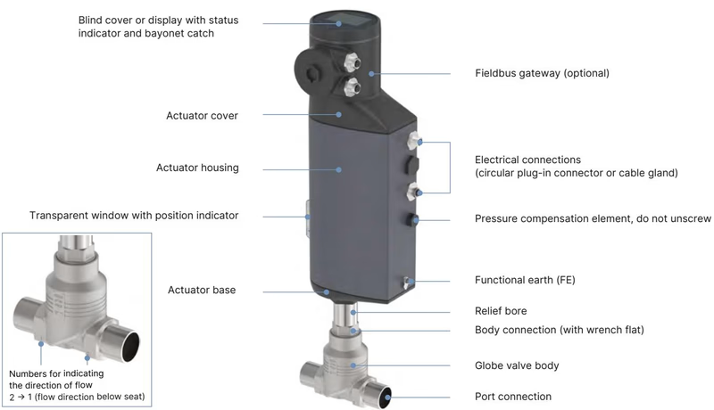
The electromotive linear actuator incorporates a brushless DC motor, mechanical reduction gearing, and a ball screw spindle that displaces the valve stem. Self-locking mechanical transmission holds the valve closed against full line pressure without drawing continuous motor current.
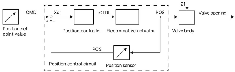
The internal displacement transducer monitors the real-time position (POS) of the electric drive shaft. The internal digital positioner compares the measured stem position with the digital setpoint value (CMD) received via EtherNet/IP or the büS interface. System deviation (Xd1) prompts motor actuation (CTRL) to restore setpoint alignment within the ±0.1% dead band.
When electrical supply voltage is disconnected, the valve stroke position can be shifted manually using a mechanical manual override mechanism located beneath the display module.
Manual Override Operating Restrictions
Lubrication Requirement
Always lubricate external threads on the valve body and replacement valve seat inserts with Klüberpaste UH1 96-402 before reassembly to maintain thread integrity and seal compression.
When removing or reinstalling the electromotive actuator, the valve must be positioned at least 1/3 open (in MANUAL operating mode) to prevent damage to the PTFE seat seal and contour cone. Secure the valve body in a holding device and tighten the body connection to the exact specification:
| Connection / Orifice Size | Tightening Torque |
|---|---|
| DN 10 / 15 | 45 ±3 Nm |
| DN 20 | 50 ±3 Nm |
| DN 25 (NPS 1) | 60 ±3 Nm |
| DN 32 / 40 | 65 ±3 Nm |
| DN 50 | 70 ±3 Nm |
The valve seat can be unscrewed from the body using the dedicated Type 3361 installation tool (Order No. 652606 for DN 25):
X.TUNE Calibration Restriction
After mounting an actuator or servicing the seat/cone assembly, execute the X.TUNE automatic adjustment function to calibrate stroke limits. Never run X.TUNE under active medium pressure. Performing calibration under pressure leads to incorrect stroke calibration and uncontrolled process behavior.
Explore similar products in our catalog


