PN16

BURKERT 346868 Type 8640 modular valve island. Features 19mm width per station, G 1/4 pressure port, 2-8 bar operating pressure, and IP20 protection.
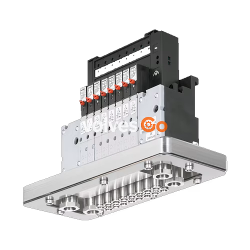
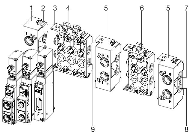
BURKERT 346868 Type 8640 modular valve island is designed to solve diverse and complex control problems due to its systematic modular construction and combination of pneumatic and electrical interfaces. By putting together a row of pneumatic modules with different numbers of valves, multiple valve functionalities may be realized on one valve unit. Electrical connectivity is achieved by either fieldbus interfaces, common connection (parallel connection technique), or multipin interfaces. Bodies and connection modules are made of high-quality plastic (polyamide) and are easy to assemble by means of the built-in snap connectors.

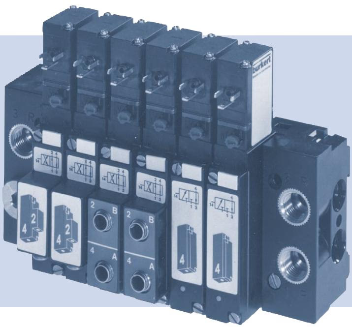
The 346868 configuration features a 19 mm width per station, utilizing Type 5470 solenoid valves. It offers a compact design, higher flexibility in the control cabinet, and simple exchange of valves.
| Product properties | Type 8640 (19 mm / Type 5470 configuration) |
|---|---|
| Body Material | PA (polyamide) |
| Seal Material | NBR |
| Width per station | 19 mm |
| Manual override | Standard |
| Number of valve slots | Max. 24 |
| Pressure range | 2...10 bar (SKU 346868 specific: 2-8 bar) |
| Flow rate $Q_{Nn}$ value air | 300 l/min measured at +20 °C, 6 bar pressure at valve inlet and 1 bar differential pressure |
| Nominal operating mode | Continuous operation (100% duty cycle) |
| Operating voltage | 24 V DC (±10% tolerance) |
| Operating medium | Oil-free or lubricated compressed dry air, neutral gases (5 μm filter recommended) |
| Compressed air quality | ISO 8573-1: 2010, Class 7.4.4 |
| Degree of protection | IP20 (IP65 in closed control cabinets / with cable plug) |
| Ambient temperature | 0 °C...+ 55 °C |
The valves consist of a 3/2-way pilot valve (Type 6106) with different electrical connection variants, a valve body with diaphragm, seat seals, and A/B connection plates. The working ports 2 (B) / 4 (A) as well as supply connection and exhaust port 1 (P) / 3 (R) are available with internal thread, plug-in coupling, or pointed hose nipples.
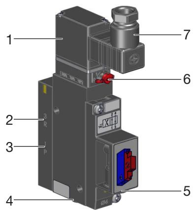
Connections:
Manual Override
To operate the valve manually, press the manual override and turn it 90° clockwise (until it stops). The manual override is locked and does not reset automatically. Only operate the manual override when the power is off.
| Symbol | Description |
|---|---|
| C | 3/2-way valve. In rest position, pressure port 1 (P/NC) closed, working port 2 (A/OUT) open after port 3 (R/NO). |
| D | 3/2-way valve. In rest position, pressure port 1 (P/NO) open after working port 2 (B/OUT), port 3 (R/NC) closed. |
| G | 4/2-way valve. In rest position, pressure port 1 (P) open after working port 2 (A), working port 4 (B) open after port 3 (R). |
WARNING
Crushed O-rings and profile seals lead to leaky blocks. Fasten each valve to the base module with 2 screws. Recommended tightening torque 0.6 ±0.1 Nm.
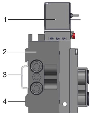
Standard rail installation:
Wall installation:
Safety Instructions
Risk of injury due to high pressure and escaping medium. Switch off the pressure before working on the device or system. Vent or drain the pipes.
Risk of injury due to electric shock. Switch off voltage before working on the device or system. Secure against reactivation. Observe any applicable accident prevention and safety regulations for electrical devices.
Explore similar products in our catalog