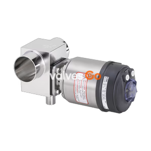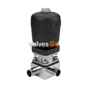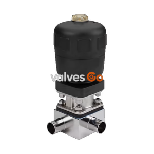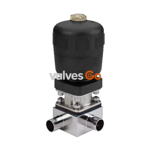
Type 2032

BURKERT 347953 (Type 2031) pneumatic 2/2-way diaphragm valve features an NC PPS piston actuator, ASME BPE weld ends DN 15, and an Advanced PTFE/EPDM diaphragm for aseptic media up to 10 bar.
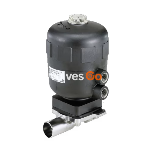
BURKERT 347953 (Type 2031) is an externally controlled 2/2-way diaphragm valve configured with a pneumatic piston actuator, an Advanced PTFE/EPDM diaphragm, and a stainless steel valve body with ASME BPE weld ends. Operating under control function A (normally closed by spring force), this valve provides zero-deadleg shut-off for ultra-pure, sterile, aggressive, and abrasive liquid or gaseous media. The valve accommodates working medium pressures from 0 to 10 bar, working temperatures from -5 °C to +143 °C, and short-term steam sterilization cycles up to +150 °C for 60 minutes.
Equipped with a compact 40 mm (size C) polyphenylene sulphide (PPS) actuator, article 347953 withstands demanding environmental conditions and is fully autoclavable. The unit features an integrated optical position indicator showing open/closed status, FKM piston seals, and a G 1/8 internal thread pilot air connection. Designed specifically for CIP and SIP cycles, this product configuration is delivered complete with a manufacturer inspection certificate 3.1 and membrane factory certificate 2.1.
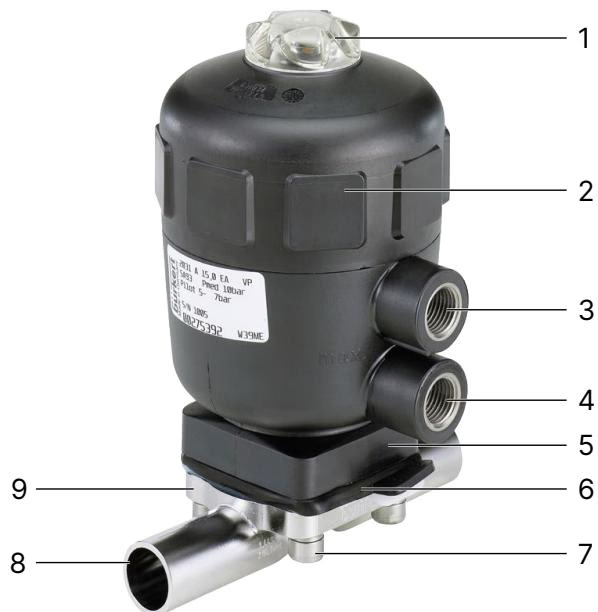
BURKERT 347953 comprises three main assemblies: the pneumatic piston actuator, the sealing diaphragm, and the stainless steel 2-way valve body:
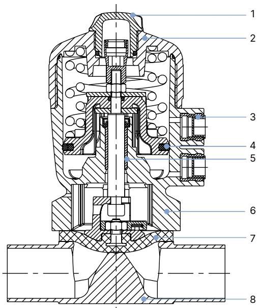
| Item | Component Name | Material Specification |
|---|---|---|
| 1 | Transparent cap | Polysulfone (PSU) |
| 2 | Actuator cover | Polyphenylene sulphide (PPS) |
| 3 | Pilot air port | Stainless steel 1.4305 |
| 4 | Piston seal | Fluor rubber (FKM) |
| 5 | Socket | Sinter metal |
| 6 | Interface / Bonnet | Polyphenylene sulphide (PPS) |
| 7 | Diaphragm | Advanced PTFE / EPDM laminate (EU) |
| 8 | Valve body | Stainless steel (1.4435 / 316L) |
| Specification Parameter | Technical Value |
|---|---|
| Valve Type | 2031 (CLASSIC Series) |
| Article Number (SKU) | 347953 |
| Circuit Function | 2/2-way, Control Function A (normally closed, NC) |
| Diaphragm Size (Orifice) | DS 8 (8 mm nominal body size) |
| Port Connection Size | DN 15 (1/2 inch) |
| Pipe Interface Standard | ASME BPE / DIN 11866 Series C (Product key SA92) |
| Valve Body Material | Stainless steel 1.4435 / 316L |
| Actuator Material / Size | PPS / Ø 40 mm (actuator size C) |
| Diaphragm Material | Advanced PTFE with EPDM backing (EU) |
| Operating Medium Pressure | 0 to 10 bar (PN 16 / ASME Class 150) |
| Pilot Pressure Range | 5.0 to 7.0 bar |
| Medium Temperature Range | -5 °C to +143 °C (steam sterilization up to +150 °C for 60 min) |
| Ambient Temperature Range | +5 °C to +140 °C (PPS size ≤ 80 mm) |
| Water Flow Coefficient Kv | 2.2 m³/h (measured at +20 °C, 4 bar inlet, 3 bar outlet) |
| Pilot Air Port Thread | G 1/8 internal thread |
| Cleaning Capabilities | CIP (Clean-in-Place) and SIP (Sterilise-in-Place) capable |
| Conformities & Certifications | FDA CFR 21, USP Class VI, EC 1935/2004, DIN EN 10204 3.1 & 2.1 |
INFO
Operating pressures up to 10 bar are permissible under static conditions (valve closed, pressure applied on one side of the weir) when using Advanced PTFE/EPDM (EU) diaphragms on size 40 actuators.
Article 347953 features ASME BPE / DIN 11866 Series C welded ends designated by Bürkert product key SA92. The dimensions below apply to diaphragm size 8, port connection DN 15 (1/2") paired with actuator size 40 (C):
| Dimension Identifier | Value (mm) | Description |
|---|---|---|
| Port connection DN | DN 15 (1/2") | Nominal tube size |
| Pipe outer diameter (Ø D1) | 12.7 mm (0.500") | Outside diameter of ASME BPE weld stub |
| Wall thickness (s) | 1.65 mm (0.065") | Tube wall thickness |
| Pipe inner diameter | 9.4 mm | Inside tube clearance |
| Face-to-face length (L) | 89 mm | Total body length end-to-end |
| Centerline-to-bottom height (h) | 9.3 mm | Height from pipe center to body underside |
| Total body height (H) | 18.8 mm | Total height of bare body casting/forging |
| Actuator outer diameter (Ø A) | 53 mm | Outer diameter of size 40 (C) actuator cover |
| Actuator bottom width (C) | 34 mm | Width across flats of actuator base interface |
| Actuator basic height (H) | 89 mm | Height from body interface to top of transparent cap |
| Actuator height with MT85 | 111 mm | Height with block mounting module interface |
| Actuator height with Type 8697 | 185 mm | Total height including Type 8697 position feedback unit |
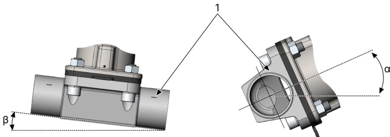
Correct installation ensures cavity-free draining and prevents thermal damage to internal elastomers:
WARNING
Always supply compressed air (5.0 to 7.0 bar) to the lower pilot port before loosening or tightening body screws on control function A valves. This lifts the compressor off the weir and prevents tearing or stretching the Advanced PTFE diaphragm during servicing.
Reassembly requires adherence to calibrated bolt torques. Excessive torque damages the PTFE sealing face, whereas insufficient torque causes external or seat leakage:
| Fastener / Component | Size / Context | Required Torque | Tolerance |
|---|---|---|---|
| Body screws (11) | Diaphragm size 8 (Advanced PTFE/EPDM) | 2.5 Nm | +10% |
| Actuator cover (2) | Actuator size 40 (C) | 25 Nm | — |
| Piston spindle nut (19) | Actuator size 40 (C) | 3.5 Nm | — |
| Position indicator (20) | Actuator size 40 (C) | 1.5 Nm | — |
| Transparent cap (21) | Polysulfone cap with O-ring | 1.5 Nm | — |
Under clean operating conditions, the pneumatic actuator requires no scheduled lubrication. Scheduled maintenance focuses on the wearing elastomer components:
| Spare Part / Tool | Description | Order Article Number |
|---|---|---|
| Seal Set | PPS Actuator size 40 (C), DS 8 (includes piston seal, lip seal, O-rings) | 011465 |
| Replacement Diaphragm | Advanced PTFE/EPDM (EU), Diaphragm size 8 (Material code PTFE L12) | 20093078 |
| Alternative Diaphragm | EPDM (AD), Diaphragm size 8 (Material code EPDM E04) | 688421 |
| Conversion Kit CF A → CF B | Converts size 40 (C) actuator to normally open (spring open) | 011678 |
| Conversion Kit CF A → CF I | Converts size 40 (C) actuator to double-acting operation | 001948 |
| Actuator Cover Wrench | Dedicated service tool for size 40 (C) and 50 (D) actuator covers | 639175 |
Explore similar products in our catalog