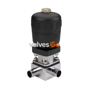
Type 2032

BURKERT 348518 (Type 2031) 2/2-way piston-operated diaphragm valve. Features a stainless steel body, PA actuator, EPDM diaphragm, and double-acting control function I. Suitable for hygienic media.
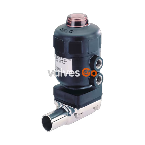
BURKERT 348518 (Type 2031) is an externally controlled 2/2-way diaphragm valve with a pneumatic piston actuator and diaphragm seal. It uses neutral gases or air to control the flow of media. The proven and robust PA (Polyamide) actuator combined with a flow-optimised stainless steel valve body ensures reliable operation in hygienic or aggressive environments. This specific model features a DN 65 weld end connection, an EPDM high-temperature diaphragm, and operates with Control Function I (double-acting). The valve is self-draining when installed in the appropriate position.
The device can be identified by its type label, which contains vital operating parameters such as control function, diaphragm size, materials, and pressure limits.
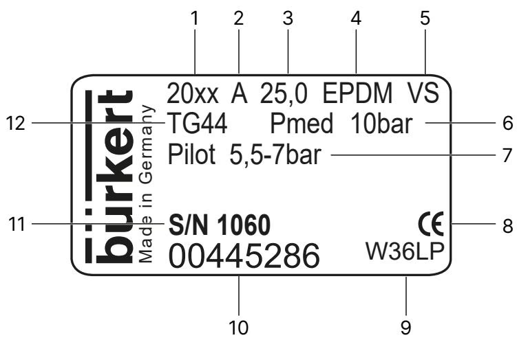
Pressure Limits
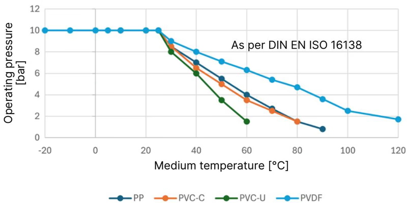
Do not exceed the maximum permissible pilot pressure or maximum permissible operating pressure. For this model, the nominal pressure is up to 7 bar, and the control pressure range is 4 to 6 bar.
The information in the pressure-temperature diagram is important for material selection. Observe the permissible operating pressure depending on the medium temperature.
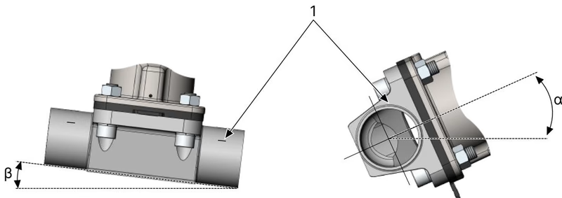
The installer and the operator are responsible for ensuring self-draining. The inclination angle should correspond to the inclination angle of the pipeline. One of the relief bores in the diaphragm bonnet for monitoring leakages must be at the lowest position.
Damage to the diaphragm or the actuator
The diaphragm and actuator can be damaged when welding the valve body into the pipeline. Remove the actuator and diaphragm from the valve body before installation.
Risk of crushing
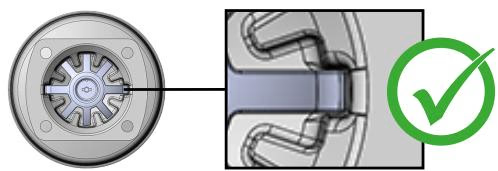
If the compressor is not positioned correctly and the actuator is actuated, this may result in injuries and damage to the device. Before actuating the actuator, ensure that the compressor is in the correct position.
For Control Function I (CF I): Connect the control medium to the upper and lower pilot air ports of the actuator.
Pilot Pressure Failure
For control function I: The valve stays in an undefined position in the event of a pilot pressure failure. To ensure a controlled restart, first pressurise the device with pilot pressure, then switch on the medium.
Risk of injury from sudden discharge of pressure
Disassembling a pressurised device can cause medium to escape unexpectedly. Before disassembly, shut off the pressure and vent all lines.
Explore similar products in our catalog