


Up to 99.8% Efficiency

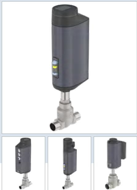
BURKERT 349372 (Type 3361) is an electromotive 2-way globe control valve with AG2 actuator (1300 N), 2" ANSI Class 150 flange, seat size 32 mm, PTFE seat seal, Kv 21 m3/h, and EtherNet/IP fieldbus gateway.
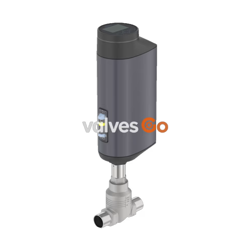
BURKERT 349372 (Type 3361) is an electromotive 2-way globe control valve engineered for high-precision throttling tasks in demanding industrial and hygienic process environments. The unit integrates a brushless DC linear actuator (size AG2, 1300 N driving force) with a ball screw transmission, driving a parabolic control cone at positioning speeds up to 6 mm/s. Flow enters below the seat (direction 2 -> 1), eliminating pressure hammer effects and ensuring process stability against line pressure fluctuations. Configured with a 2" ANSI B16.5 Class 150 flanged stainless steel body (CF3M) and a 32 mm orifice seat, the valve achieves a nominal flow rate (Kvs) of 21 m³/h (water) with an equal percentage flow profile and a 50:1 theoretical rangeability.
Operating on 24 V DC, this model incorporates an integrated positioner with an internal positioning dead band of ±0.1%, an EtherNet/IP fieldbus gateway, and a local blind cover interface equipped with internal pushbuttons and DIP switches. Sealing integrity is maintained by a spring-loaded PTFE chevron packing gland alongside a replaceable PTFE seat seal disc rated to DIN EN 60534-4 Leakage Class VI up to 16 bar(g). The wetted stainless steel materials comply with EC Regulation 1935/2004 for food contact, and the entire outer housing is rated IP65/IP67 and NEMA 4X with Ecolab-certified chemical washdown resistance.
| Specification Parameter | Value / Detail |
|---|---|
| Product Model & Type | BURKERT 349372 (Type 3361) |
| Valve Construction | 2-way straight globe control valve |
| Pipeline Nominal Diameter | DN 50 (2") |
| Pipe Connection Standard | Flange according to ANSI B16.5 Class 150 (face-to-face FTF 37 per DIN EN 558-2) |
| Orifice / Seat Size | 32 mm (1 1/4") |
| Flow Factor Kvs | 21 m³/h (water per DIN EN 60534-2-4) |
| Flow Factor Cv | 24.3 gal/min |
| Flow Characteristic | Equal percentage (theoretical rangeability 50:1) |
| Flow Direction | Under seat (direction 2 -> 1, against closing direction) |
| Operating Pressure Range | 0.00 to 16.00 bar(g) |
| Nominal Pressure Class | Class 150 (ASME B16.34) / PN 25 (DIN EN 1333) |
| Seat Leakage Performance | Class VI according to DIN EN 60534-4 (bubble-tight soft seal) |
| Operating Medium Temperature | -10 °C to +130 °C (recommended for PTFE seat seals) |
| Ambient Operating Temperature | -25 °C to +65 °C (refer to derating curves for module installations) |
| Kinematic Viscosity Limit | Up to 600 mm²/s |
| Operating Supply Voltage | 24 V DC ±10% (maximum residual ripple 10%) |
| Operating Current Draw | Max. 3 A at peak load; additional 2 A at minimum operating temperature |
| Standby Power Draw | 2 to 5 W |
| Actuator Size & Driving Force | AG2 / 1300 N nominal thrust |
| Linear Travel Speed | 6 mm/s |
| Typical Closing Time | 4.5 s (stroke and travel-speed dependent) |
| Position Control Dead Band | ±0.1% |
| Fail-Safe Operation (Power Loss) | Static blocking in last physical position (no internal electrical energy pack) |
| Digital Communications | büS service interface + integrated EtherNet/IP fieldbus gateway |
| Protection Class & Degree | Class III (DIN EN 61140); IP65 / IP67 (DIN EN 60529), NEMA 4X |
| Food & Washdown Standards | EC Regulation 1935/2004 compliant; Ecolab F&E/P3-E No. 40-1 test passed |
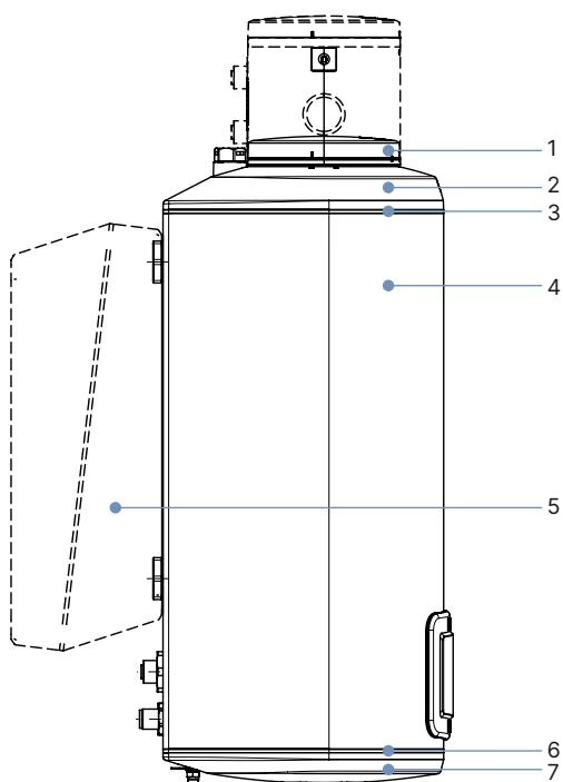
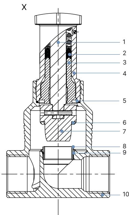
The Type 3361 valve assembly combines a powder-coated aluminium and technical polymer actuator casing with an investment-cast austenitic stainless steel valve body. The wetted trim incorporates precision-machined 1.4571 (316Ti) stainless steel internals and pure PTFE soft-sealing components.
| Item No. | Actuator Sub-Assembly | Material Specification |
|---|---|---|
| 1 | Blind Cover / Gateway Module Housing | PPS (Polyphenylene sulphide) |
| 2 | Actuator Upper Cover | PPS |
| 3 | Housing Static Seals | EPDM |
| 4 | Main Actuator Housing | Powder-coated die-cast aluminium |
| 6 | Inter-Housing Gaskets | EPDM |
| 7 | Actuator Bottom Base | PPS |
| Item No. | Valve Part Component | Material Specification |
|---|---|---|
| 1 | Valve Spindle | Stainless steel 1.4401 (316) / 1.4404 (316L) |
| 2 | Spindle Packing Gland | Filled PTFE V-rings with Belleville spring preloading |
| 3 | Spindle Guiding Bushing | Stainless steel 1.4404 (316L) |
| 4 | Packing Gland Tube | Stainless steel 1.4401 (316) |
| 5 | Body Joint Seal Ring | Graphite or pure PTFE |
| 6 | Seat Sealing Element | PTFE sealing disc insert |
| 7 | Parabolic Control Cone | Stainless steel 1.4571 (316Ti) |
| 8 | Replaceable Threaded Valve Seat | Stainless steel 1.4571 (316Ti) |
| 9 | Valve Seat O-ring | EPDM or PTFE |
| 10 | Valve Body Casting | Cast stainless steel CF3M (equivalent to AISI 316L) |
Dimensions below detail the Type 3361 DN50 flanged configuration conforming to ANSI B16.5 Class 150 face-to-face standards (FTF 37 per DIN EN 558-2).
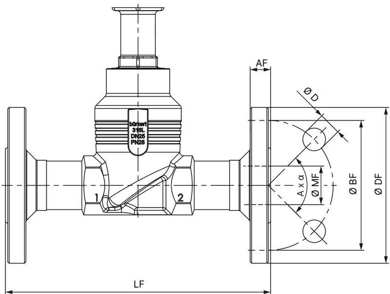
| Nominal Diameter | Flange OD (∅ DF) | Face-to-Face (LF) | Bolt Circle (∅ BF) | Flange Thick. (AF) | Hole Dia. (∅ D) | Bolt Pattern (A × α) | Raised Face (∅ MF) |
|---|---|---|---|---|---|---|---|
| 2" (DN 50) | 152 mm | 254 mm | 120.7 mm | 19.1 mm | 19.1 mm | 4 × 90° | 52.6 mm |
Article 349372 features a 32 mm orifice seat inside a DN50 valve body, yielding a full-stroke Kvs value of 21 m³/h. The control contour is characterized by an equal percentage curve according to DIN EN 60534-2-4 with a 50:1 theoretical rangeability. At 5% stroke, the certified minimum controllable flow (KvR) is 0.48 m³/h.
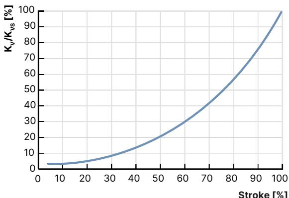
| Orifice Size | Actuator Force | Max. Delta P | Kv at 5% | Kv at 10% | Kv at 20% | Kv at 30% | Kv at 40% | Kv at 50% | Kv at 60% | Kv at 70% | Kv at 80% | Kv at 90% | Kvs (100%) |
|---|---|---|---|---|---|---|---|---|---|---|---|---|---|
| 32 mm (1 1/4") | 1300 N | 16 bar(g) | 0.48 | 0.60 | 0.90 | 1.3 | 2.1 | 3.2 | 4.6 | 6.9 | 11.6 | 16.0 | 21.0 m³/h |
INFO
Kv values are determined using ambient water under standardized test conditions in accordance with DIN EN 60534-2-4. Under compressible fluid service (gases or dry steam), flow calculations must adhere to standard gas sizing formulas with flow oriented against the closing direction (under seat).
Maximum allowable media and ambient working conditions are interdependent. Operating article 349372 requires consideration of standard ANSI Class 150 pressure-temperature curves, actuator heat dissipation, and soft-seal thermal limits.
Electrical connection is established via industrial M12 circular connectors located on the actuator base and the top-mounted fieldbus gateway module.
| Pin Number | Signal Assignment | Electrical Characteristics |
|---|---|---|
| 1 | Digital Input + | 0 to 5 V = log "0", 10 to 30 V = log "1" |
| 2 | GND (Digital Return) | Common ground reference for binary I/O |
| 3 | Digital Output 2 + | PNP transistor output, max. 100 mA current limit |
| 4 | Digital Output 1 + | PNP transistor output, max. 100 mA current limit |
| 5 | Analogue Output - | Galvanically isolated current/voltage return |
| 6 | Analogue Output + | 0/4 to 20 mA (load 0 to 800 Ω) or 0 to 5/10 V (max. 10 mA) |
| 7 | Set-Point / Analogue Input - | Differential analog setpoint return |
| 8 | Set-Point / Analogue Input + | 0/4 to 20 mA (input resistance 70 Ω) or 0 to 5/10 V (22 kΩ) |
| Pin Number | Signal Assignment | Electrical Characteristics |
|---|---|---|
| 1 | CAN Shield | Cable braid grounding shield |
| 2 | Operating Voltage + | 24 V DC ±10% (max. residual ripple 10%) |
| 3 | GND / CAN_GND | Power ground / bus ground reference |
| 4 | CAN_H | CAN high dominant signal level |
| 5 | CAN_L | CAN low dominant signal level |
| Pin Number | Signal Assignment | Ethernet Direction |
|---|---|---|
| 1 | Transmit + (Tx+) | Differential transmit positive pair |
| 2 | Receive + (Rx+) | Differential receive positive pair |
| 3 | Transmit - (Tx-) | Differential transmit negative pair |
| 4 | Receive - (Rx-) | Differential receive negative pair |
Article 349372 functions as an autonomous closed-loop positioning valve. An internal linear displacement transducer monitors the precise vertical stroke (POS) of the actuator spindle. The microcontroller continuously compares the actual valve position with the target setpoint (CMD) received either over EtherNet/IP or through the analog standard input.
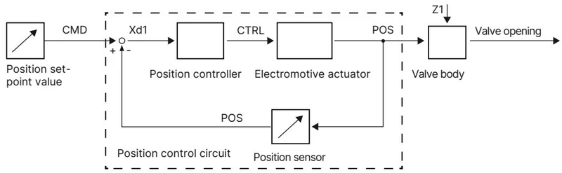
When a control deviation (Xd1) occurs, the electronics drive the brushless DC motor via the manipulated variable (CTRL), repositioning the ball screw until the physical position matches setpoint criteria within the ±0.1% dead band. In the event of control voltage interruption, this configuration blocks statically in its current position.
Installation requires standard ANSI Class 150 flange bolting, with preferred mounting orientation upright. The actuator mechanism and valve seat may be serviced or replaced without removing the body casting from the pipeline.
Mechanical Manual Override Restrictions
The mechanical manual override must only be engaged when the actuator is completely de-energized. Use a 3 mm Allen key to depress and turn the override spindle counter-clockwise to open, clockwise to close. Never exceed the maximum torque limit of 2 Nm, as excessive force damages internal geartrain limits.
| Mechanical Joint Connection | Fastener / Fitting Size | Specified Torque Value |
|---|---|---|
| Body Connection to Valve Body (DN 50) | Body neck thread with wrench flats | 70 ± 3 Nm (52 ± 2 lbf ft) |
| Valve Seat Ring Installation (Size 32) | Threaded replaceable seat insert | 65 + 5 Nm |
| Spindle Guide Bushing (ø14 mm spindle) | Body neck internal thread | 60 Nm |
| Actuator Housing Fastening Screws | 4x T25 hexalobular screws | 5.0 Nm |
| Fieldbus Gateway Mounting Screw | 1x 3 mm socket head screw | 1.1 Nm |
Calibration Routine (X.TUNE)
Following any mechanical disassembly, spindle packing replacement, or valve seat exchange, run the integrated X.TUNE self-calibration routine to map mechanical stop boundaries. Run X.TUNE only on a completely depressurized piping system. Press and hold the internal OPEN and CLOSE pushbuttons simultaneously for 5 seconds until the LED ring illuminates solid orange.
| Accessory / Spare Description | Article Order Number |
|---|---|
| USB büS Interface Set 1 (Type 8923 with power supply and cables) | 772426 |
| USB büS Interface Set 2 (Type 8923 without power pack) | 772551 |
| büS M12 to Micro-USB Configuration Cable Adapter | 774931 |
| SIM Card for Device Parameter Cloning and Firmware Transfer | 291773 |
| M12 Female Cable Connector (8-pin, A-coded, length 2.0 m) for Port X1 | 919061 |
| M12 Female Cable Connector (4-pin, A-coded, length 5.0 m) for Port X3 Power | 918038 |
| M12 D-coded to RJ45 Industrial Ethernet Cable (length 5.0 m) for Port X7 | 775053 |
| Replacement Valve Seat Set (Seat Size 32, DN 50 body, with seals) | 262176 |
| Replacement Parabolic Control Cone Set (PTFE/Steel, Seat Size 32, DN 50) | 226969 |
| Packing Gland Seal Replacement Kit (Spindle ø14 mm, DN 25 to DN 50) | 285722 |
| Specialized Seat Installation Socket Tool (DN 50 valve body) | 652609 |
| Klüberpaste UH1 96-402 Assembly Lubricant (Tube) | Standard Burkert Spare |
Explore similar products in our catalog


