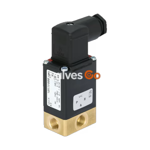
PN16

Burkert 349759 (Type 6281) servo-assisted 2/2-way solenoid valve. Features brass body, G 1 1/2 thread, NBR seal, 230V, and ATEX/IECEx terminal box for hazardous locations.
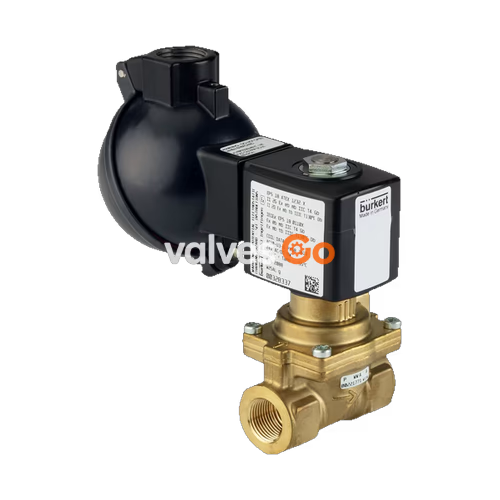
BURKERT 349759 Type 6281 is a servo-assisted 2/2-way diaphragm valve designed for controlling, shutting off, and dosing neutral media. This specific model features a brass body, G 1 1/2 internal thread, NBR seal, and operates at 230V (50/60 Hz). It is equipped with an ATEX/IECEx approved terminal box without a fuse, making it highly suitable for hazardous locations.
A minimum differential pressure is always required for the valve to function. The standard brass body meets European drinking water requirements. To reduce electrical power consumption during operation, coils with integrated Kick-and-Drop (KD) electronics featuring double coil technology are available within the Type 6281 family.
| Property | Description |
|---|---|
| Seal Material | NBR |
| Body Material | Brass acc. to DIN EN 50930-6 |
| Inner Valve Parts | Stainless steel, brass, plastic (PPS) |
| Orifice | 40 mm (DN 40) |
| Duty Cycle | 100 % continuous operation |
| Voltage Tolerance | ±10 % |
| Degree of Protection | IP65 with terminal box |
| Installation | As required, preferably with actuator upright |
| Symbol | Description |
|---|---|
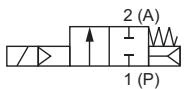 | Circuit function A (CF A) 2/2-way solenoid valve Servo-controlled Normally closed |
Explosion Protection (ATEX/IECEx)
Note on Hazardous Locations
The maximum medium temperature must never exceed the permitted temperature class (T4: +135 °C, T5: +100 °C, T6: +85 °C) minus 5 K.
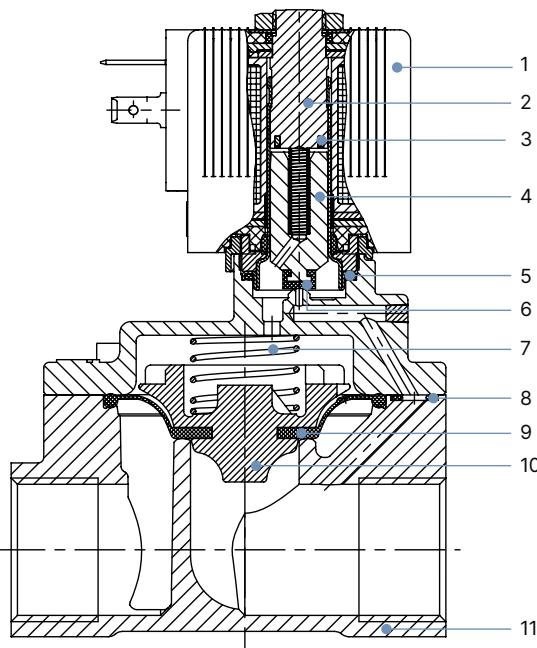
| No. | Element | Material |
|---|---|---|
| 1 | Coil | Polyamide or epoxy |
| 2 | Stopper | Stainless steel 1.4113 |
| 3 | Shading ring | Cu (brass variant) |
| 4 | Magnetic core | Stainless steel 1.4113 |
| 5 | O-ring | NBR |
| 6 | Core seal | NBR |
| 7 | Spring | Stainless steel 1.4310 |
| 8 | O-ring | NBR |
| 9 | Diaphragm | NBR |
| 10 | Diaphragm holder | PPSGF40 |
| 11 | Valve body | Brass acc. to DIN EN 50930-6 |
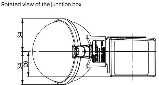
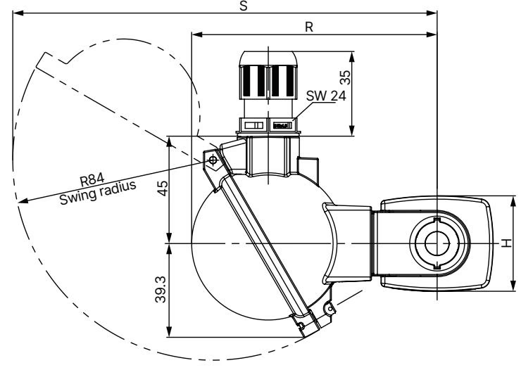
Dimension Notes
Risk of injury from high pressure
Before loosening lines or valves, switch off the pressure and vent the lines.
Risk of injury from electric shock
Before reaching into the device or the system, switch off the power supply and secure it against reactivation. Observe the applicable accident prevention and safety regulations for electrical devices.
Risk of injury due to improper installation
Installation must be carried out by authorised technicians only and with the appropriate tools. Secure the system against unintentional activation and ensure a controlled restart after installation.
Before Installation:
Installation:
Explore similar products in our catalog