

PN16

Burkert 356874 (Type 0142) is a servo-assisted 2/2-way normally open (CF B) diaphragm valve with DN50 PVC body, 63 mm gluing sleeves, FKM seals, 48 V AC coil, and 0.5 to 6 bar operating pressure range.
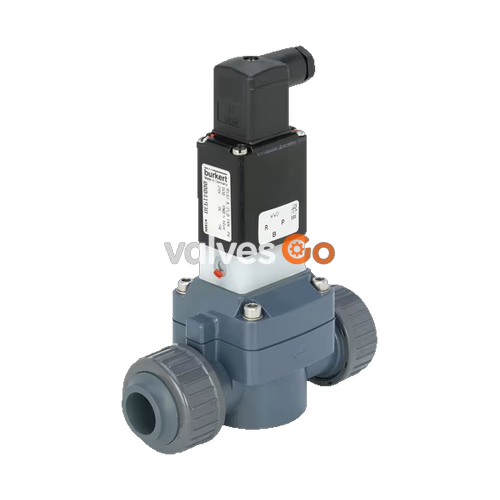
BURKERT 356874 (Type 0142) is a servo-assisted 2/2-way diaphragm solenoid valve engineered for controlling, shutting off, and dosing aggressive, contaminated, and high-purity liquid or gaseous media. Configured in Circuit Function B (normally open), the main valve remains open by spring force when de-energized and closes upon electrical actuation. The valve requires a minimum differential operating pressure of 0.5 bar to open and close reliably. The media-contacting assembly features complete galvanic separation, isolating internal electromagnetic components from corrosive fluids via an FKM isolating diaphragm and an inert PVDF pilot structure.
Equipped with a solid PVC valve body, true union connection ends with d 63 mm adhesive gluing sleeves, and an epoxy-encapsulated Class H solenoid coil, the unit handles operating pressures from 0.5 to 6.0 bar. A lockable manual override is integrated directly onto the housing for commissioning and maintenance without electrical control signals.
| Parameter | Specification |
|---|---|
| Article number | 356874 |
| Type series | 0142 |
| Circuit function | B (2/2-way, normally open) |
| Nominal diameter (DN) | DN 50 (2") |
| Orifice size | 50.0 mm |
| Pilot orifice | 2.0 mm |
| Kv value (water, +20 °C) | 36.0 m³/h |
| QNn value (air) | 38,700 l/min |
| Operating pressure range | 0.5 to 6.0 bar |
| Body material | PVC (Polyvinyl chloride) |
| Seal material | FKM (fluor rubber) |
| Pilot stage material | PVDF (Polyvinylidene fluoride) |
| Nominal voltage | 48 V AC (50/60 Hz) |
| Voltage tolerance | ±10% |
| Electrical power consumption | Inrush: 20 VA; Holding: 11 VA / 5 W |
| Duty cycle | 100% ED continuous operation |
| Switching times (at +20 °C, 6 bar) | Opening: 100 ms to 800 ms; Closing: 1000 ms to 4000 ms |
| Process connection | True union joint with solvent cement / gluing sleeve d 63 mm |
| Fluid viscosity | Max. 21 mm²/s |
| Permissible medium temperature | 0 °C to +50 °C |
| Permissible ambient temperature | 0 °C to +40 °C |
| Enclosure rating | IP65 (with cable plug DIN EN 175301-803 Form A) |
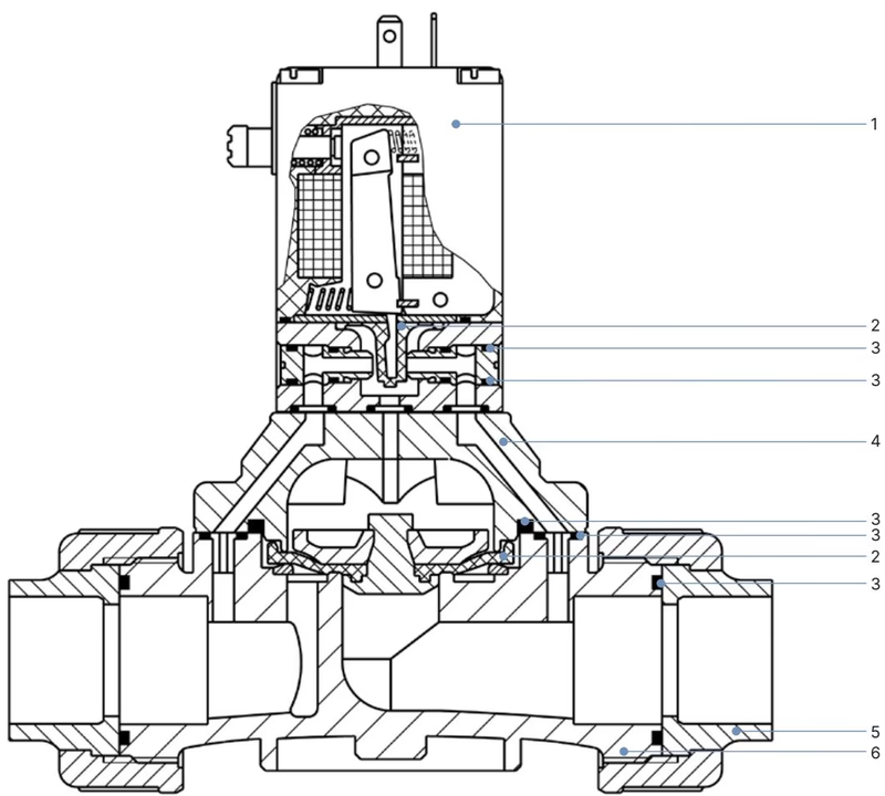
| Item No. | Component | Material |
|---|---|---|
| 1 | Coil body | Epoxy (Thermal class H) |
| 2 | Diaphragm | FKM |
| 3 | O-ring | FKM |
| 4 | Cover | PVC |
| 5 | Socket fitting (true union) | PVC |
| 6 | Valve body | PVC |
| — | Pilot valve internals | PVDF |
FKM seals provide chemical resistance against oxidizing acids, oxidizing substances, and inorganic salt solutions. PVC components allow broad compatibility with acidic and basic industrial process streams within the specified thermal limits.
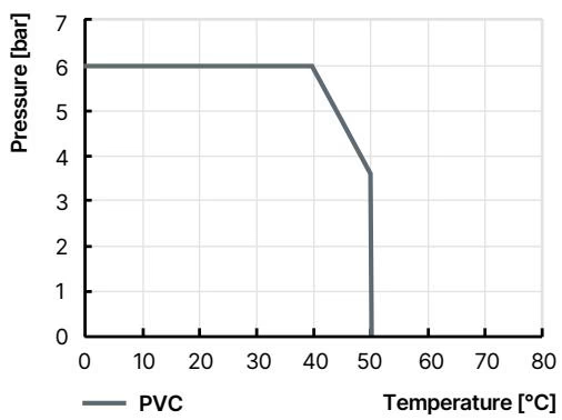
Operating pressure limits for PVC bodies decrease as the medium temperature rises. The valve must be operated within the defined envelope below:
| Medium Temperature (°C) | Maximum Allowable Operating Pressure (bar) |
|---|---|
| 0 °C to +20 °C | 6.0 bar |
| +30 °C | 5.0 bar |
| +40 °C | 3.5 bar |
| +50 °C | 1.5 bar |
Continuous Operation Guidance
When installed in continuous duty applications subject to extended periods of non-actuation, operate the valve at least 1 to 2 cycles per day to maintain functional reliability.
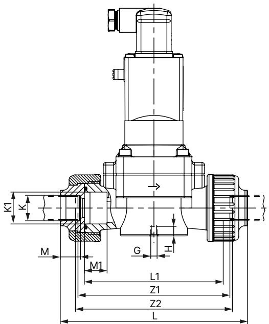
All dimensions are in millimeters (mm):
| Parameter | Value (DN 50 / Pipe ∅ 63 mm) |
|---|---|
| Pipe Outer Diameter (∅) | 63 mm |
| A (Actuator width) | 160 mm |
| B (Overall height) | 212 mm |
| C (Center to base) | 115 mm |
| D (Port center to bottom) | 42.5 mm |
| E (Base mounting span) | 104.5 mm |
| F (Mounting hole spacing) | 44.5 mm |
| G (Thread size) | M8 |
| H (Thread engagement depth) | 15 mm |
| L (Overall body length with union) | 268 mm |
| L1 (Body face-to-face length) | 192 mm |
| K / K1 (Socket bore diameter) | 63.2 mm / 63.2 mm |
| M / M1 (Socket insertion depth) | 38 mm / 33 mm |
| Z1 (Laying length between socket stops) | 198 mm |
Mechanical Strain Warning
Do not use the solenoid coil as a lever arm during assembly or alignment. The valve body must be installed free of mechanical stress, bending moments, or piping misalignment.
The valve is equipped with a mechanical manual override on the pilot body to permit manual actuation during testing or electrical interlock:
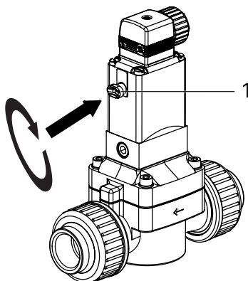
Leakage from Missing O-Rings
Never disassemble the manual override assembly while the line is pressurized. Loss or misalignment of the manual override O-rings will lead to external leakage of the pressurized process fluid.
Electrical connection is established via a cable plug conforming to DIN EN 175301-803 Form A (such as Bürkert Type 2518 or Type 2508):
Risk of Electric Shock and Overheating
Failure to connect the protective ground conductor creates a risk of electric shock. On alternating current (AC) supplies, a mechanically seized plunger prevents the magnetic circuit from closing, causing high inrush current, coil overheating, and subsequent thermal failure.
| Fault Symptom | Probable Cause | Corrective Action |
|---|---|---|
| Valve does not switch | Coil circuit interrupted or electrical short circuit | Test coil resistance and supply voltage (48 V AC) |
| Operating pressure out of specification (< 0.5 bar or > 6.0 bar) | Adjust system pressure into the 0.5–6.0 bar window | |
| Manual override locked in position | Return manual override 90° counterclockwise | |
| Valve does not close | Internal valve chambers soiled or obstructed | Disassemble and flush internal flow channels |
| Manual override engaged | Reset manual override to normal position | |
| Pilot restrictor or pilot bore hole clogged | Clean pilot bores and inlet restrictor; check upstream 500 µm filter |
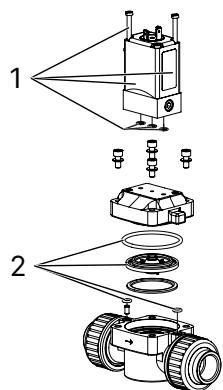
When ordering replacement assemblies, reference article number 356874 and specify the required kit item:
Explore similar products in our catalog


