PN25

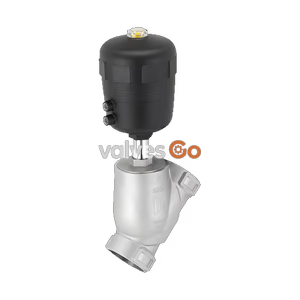
BURKERT 368999 (Type 2100) is a pneumatically operated 2/2-way angle seat valve with DN 40 SMS 3008 weld ends, flow-above-seat design for steam and gases, PTFE seat seal, and -0.9 to 16 bar operating pressure.
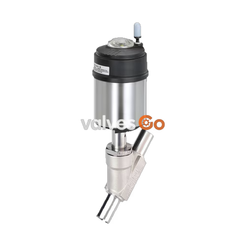
BURKERT 368999 (Type 2100) is a pneumatically operated 2/2-way ELEMENT angle seat valve engineered for decentralized process automation in steam and gaseous media applications. The valve features a cast stainless steel CF3M body with DN 40 SMS 3008 weld connections (tube outer diameter 38 mm x 1.2 mm wall thickness), providing an installation face-to-face length of 182 mm and a water flow factor Kv of 35 m³/h. Designed in Control Function A (normally closed by spring force), this valve variant directs media flow above the seat, where process pressure assists tight shut-off up to 16 bar(g). Stem sealing is maintained by a self-adjusting PTFE V-ring packing gland with stainless steel spring compensation, rated for vacuum conditions down to -0.9 bar(g) and media temperatures from -10 °C to +185 °C.

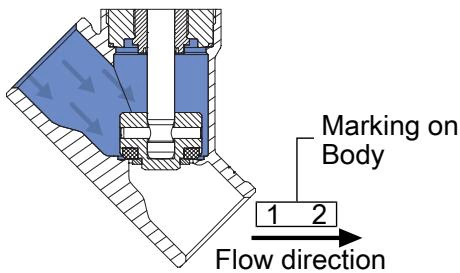
BURKERT 368999 operates under Control Function A (CF A). In the unpressurized rest position, internal actuator return springs hold the stainless steel swivel plate firmly against the PTFE valve seat. Actuating air fed to pilot air port 1 lifts the piston and spindle assembly to open the flow path. Because this specific configuration directs media above the seat (flow-to-close), line pressure works in the closing direction, reinforcing shut-off tightness against the valve orifice.
DANGER: Bursting Lines from Liquid Media Water Hammer
Valves configured with flow direction above the seat must only be used for steam, gases, and vapours. In liquid media service, closing against the flow stream creates severe water hammer (hydraulic pressure shocks) that can burst pipelines, valve bodies, and connected process equipment. Do not use this valve configuration on liquid media under any operational circumstances.
Nominal performance data for BURKERT 368999 aligns with international pressure equipment standards PN 25 (DIN EN 1333) and Class 150 (DIN EN 1759 / ASME B16.34).
| Specification Parameter | Value |
|---|---|
| Valve Type | 2100 ELEMENT |
| Article Number | 368999 |
| Circuit Function | 2/2-way, Control Function A (normally closed, NC) |
| Flow Direction | Above the seat (flow to close) |
| Port Size / Orifice | DN 40 (nominal seat diameter 40 mm) |
| Process Connection | SMS 3008 weld end (38.0 mm OD x 1.2 mm wall thickness x 35.6 mm ID) |
| Face-to-Face Installation Length | 182 mm |
| Flow Coefficient Kv (Water, +20 °C, 1 bar Δp) | 35 m³/h |
| Maximum Operating Pressure | 16 bar(g) |
| Vacuum Capability | Down to -0.9 bar(g) |
| Pilot Pressure Range | 2.7 bar(g) to 10 bar(g) |
| Control Medium | Neutral gases, air |
| Pilot Air Connection | Push-in connector, OD 6 mm (1/4 inch) |
| Permissible Operating Media | Steam, neutral gases, gaseous solvents, and vapours |
| Fluid Temperature Range | -10 °C to +185 °C |
| Ambient Temperature Range | -10 °C to +60 °C (push-in pneumatic connector) |
| Sound Pressure Level | < 70 dB(A) |
| Seat Leakage Class | Leakage rate A according to DIN EN 12266-1 |
| Degree of Protection | IP65 / IP67 according to EN 60529, NEMA Type 4X |
| Hygiene Conformity | Food (EC) 1935/2004 compliant wetted materials, CIP / SIP capable |
Operating pressure limits decrease with higher process media temperatures in accordance with DIN EN 12516-1 (PN 25) and ASME B16.34 (Class 150):
Wetted and non-wetted materials are selected for chemical compatibility and durability in industrial process environments. Packing gland and actuator lubricants comply with classification NSF H1.
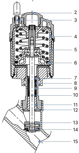
| Item No. | Component Part | Material Specification |
|---|---|---|
| 1 | Ground terminal | Stainless steel 1.4301 / 1.4305 (supplied on ATEX options) |
| 2 | Optical position indicator | Polysulfone (PSU) transparent cap |
| 3 | Pilot air ports | Polypropylene (PP) push-in connector (6 mm / 1/4") |
| 4 | Actuator cover | Polyphenylene sulphide (PPS) |
| 5 | Actuator casing | Stainless steel 1.4561 (316Ti) |
| 6 | Piston seal | FKM |
| 7 | Spring assembly | Stainless steel 1.4310 |
| 8 | Spindle guide pipe | Stainless steel 1.4401 (316) / 1.4404 (316L) |
| 9 | Packing gland | Filled PTFE V-rings with stainless steel spring compensation |
| 10 | Spindle (stem) | Stainless steel 1.4401 (316) / 1.4404 (316L) |
| 11 | Spindle guide bushing | PEEK |
| 12 | Body seal | Graphite (PTFE optional) |
| 13 | Swivel plate | Stainless steel 1.4401 (316) / 1.4404 (316L) |
| 14 | Seat seal | PTFE |
| 15 | Valve body | Cast stainless steel CF3M (316L equivalent) |
BURKERT 368999 can be installed in any orientation, with the actuator in the upright vertical position preferred. Flow must enter above the seat in accordance with the cast body direction arrow.
WARNING: Dismantle Actuator Before Welding
Before welding the CF3M valve body into the pipeline, dismantle the pneumatic actuator from the body. Welding heat conducts through the metal structure and destroys internal actuator components, piston seals, and spindle packing.
| Valve Size | Actuator Size | Tightening Torque [Nm] | Tolerance [Nm] |
|---|---|---|---|
| DN 15 | 40 (C), 50 (D), 63 (E) | 45 | +10 / -5 |
| DN 20 | 40 (C), 50 (D), 63 (E), 80 (F) | 50 | +10 / -5 |
| DN 25 | 50 (D), 63 (E), 80 (F) | 60 | +10 / -5 |
| DN 32 | 63 (E), 80 (F), 100 (G) | 65 | +10 / -5 |
| DN 40 | 63 (E), 80 (F), 100 (G), 125 (H) | 65 | +10 / -5 |
| DN 50 | 63 (E), 70 (M), 80 (F), 90 (N), 100 (G), 125 (H) | 70 | +10 / -5 |
| DN 65 | 80 (F), 100 (G), 125 (H) | 70 | +10 / -5 |
| DN 80 | 125 (H), 130 (P) | 120 | +10 / -5 |
The pilot air connections can be positioned continuously through 360° to accommodate pipe layout constraints.
CAUTION: Observe Rotation Direction
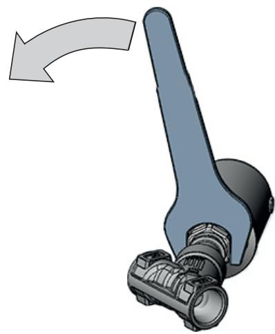
Pressurize pilot air port 1 with 5 bar air to open the valve before turning. Apply an open-end wrench to the drive connection hexagon while holding the body connection hexagon with a second wrench. Turn only in the counterclockwise direction indicated on the actuator casing to avoid loosening the body thread connection.
The ELEMENT design enables direct mounting of automated top-mounted control units without external tubing, creating complete valve systems (such as Type 8801-YE):
Routine inspection protects system integrity and prevents unplanned downtime. The visual inspection points indicated below must be checked periodically.
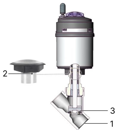
| Inspection Point | Observed Condition | Required Maintenance Action |
|---|---|---|
| Media connectors (1) | Medium leaking at weld joints or pipeline interface | Re-align and repair pipeline connections |
| Relief bore (2) | Medium or pilot air leaking from actuator relief bore | Replace spindle packing gland or actuator assembly |
| Swivel plate seat (3) | Media leaking downstream past closed valve seat | Replace valve swivel plate seat seal set |
Explore similar products in our catalog