

PN16

BURKERT 378346 (Type 8640) is a 7-bank pneumatic valve block with 19 mm station width, G 1/4 supply ports, D6 push-in bottom working ports, 2-10 bar operating pressure, and DIN-rail mounting.
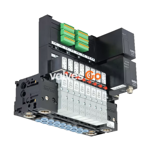
BURKERT 378346 is a 7-bank modular pneumatic valve block from the Type 8640 system, configured with a 19 mm station width and equipped with Type 5470 rocker solenoid valves. Built on modular MP05 polyamide base segments, the block provides common pneumatic supply and exhaust channels while allowing individual valve actuation through single wiring connections. The unit operates within a pressure range of 2.0 to 10.0 bar, supplying a nominal airflow rate ($Q_{Nn}$) of 300 l/min per station through bottom-oriented D6 push-in working connections.
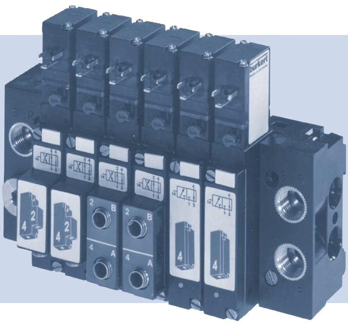
BURKERT 378346 consists of interlocking pneumatic base modules framed by dedicated left and right connection units. The modular structure eliminates custom piping between adjacent valves through integrated internal distribution channels for supply channel 1 (P) and exhaust channel 3 (R).
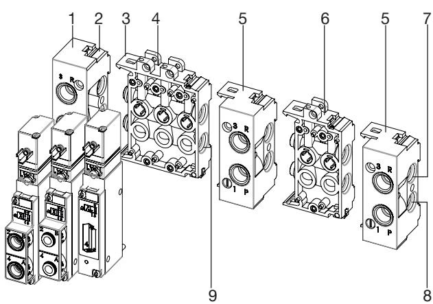
| Item | Component Designation | Function Description |
|---|---|---|
| 1 | Left connection module | Pneumatic supply inlet and exhaust port interface |
| 2 | Latch tab | Mechanical positioning guide for adjoining base blocks |
| 3 | Latch hook | Snap-locking retention hook for rigid module interlocking |
| 4 | Base module (3-fold) | Multi-station pneumatic intermediate body with shared channels |
| 5 | Right connection module | End plate termination module or auxiliary pressure stage separator |
| 6 | Base module (2-fold) | Multi-station pneumatic intermediate body |
| 7 | Exhaust channel 3 (R) | Shared exhaust manifold line |
| 8 | Supply channel 1 (P) | Shared pneumatic supply pressure channel |
| 9 | O-ring | Module inter-channel elastomer seal |
Assembly relies on lower latch hooks snapping into the preceding module's grooves, followed by upper latch hook engagement. Each module interface is sealed using two lubricated O-rings to prevent pressure loss across the internal channels.
The individual valve stations feature Type 5470 solenoid valves driven by integrated Type 6106 rocker pilot valves. A tilting armature supported by a pivot bearing executes minimal angular displacement inside the pilot body, actuating the pneumatic diaphragm without frictional slide wear or need for base lubrication.
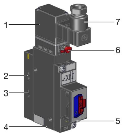
| Item | Designation | System Assignment |
|---|---|---|
| 1 | Pilot valve Type 6106 | Rocker-style electromagnetic pilot control unit |
| 2 | Exhaust port 3 | Common internal venting line (R) |
| 3 | Pressure port 1 | Common internal pneumatic supply line (P) |
| 4 | Working port 4 | Service output port B (actuator line) |
| 5 | Working port 2 | Service output port A (actuator line) |
| 6 | Manual override | Mechanical override switch for testing and maintenance |
| 7 | Cable plug Type 2516 / 2506 | DIN EN 175301-803 Form C electrical plug interface |
Each Type 5470 valve incorporates an integrated manual override to actuate the valve mechanics during commissioning or electrical downtime.
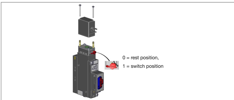
To engage manual mode, press the manual override down and rotate it 90° clockwise until mechanical stop. The override locks in position without automatic return. Manual operation must only be executed when electrical power is switched off. Unlock the override fully before resuming normal electrical control.
Type 5470 valves are available as standard 4/2-way valves (Circuit function G) or 3/2-way valves (Circuit functions C and D). A 4/2-way valve can be converted in the field into a 3/2-way valve by sealing one working port with a dedicated plug stopper.
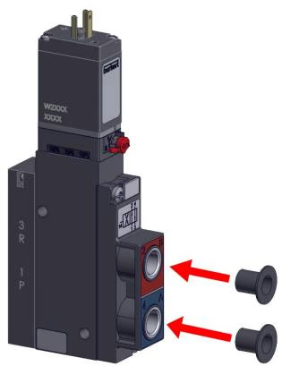
| Port 2 | Port 4 | Resulting Circuit Function | Function State Description |
|---|---|---|---|
| Closed | Open | Circuit Function C (CF C) | 3/2-way valve, normally closed (NC) in rest position |
| Open | Closed | Circuit Function D (CF D) | 3/2-way valve, normally open (NO) in rest position |
| Specification Parameter | Value / Range |
|---|---|
| Station Pitch / Width | 19 mm per station |
| Number of Valve Stations | 7-bank (7 slots) |
| Orifice Size | DN 4.0 mm |
| Flow Rate $Q_{Nn}$ (Air) | 300 l/min (at +20 °C, 6 bar inlet, 1 bar Δp) |
| Operating Pressure Range | 2.0 bar to 10.0 bar (overpressure to atmospheric) |
| Pilot Pressure Requirement | 2.0 to 10.0 bar (must reach at least 70% of operating pressure) |
| Minimum Pressure Difference | 2.0 bar minimum differential between port 1 and port 3 |
| Supply Port 1 (P) / Exhaust Port 3 (R) | G 1/4 female thread |
| Working Ports 2 (A) and 4 (B) | Push-in fittings for 6 mm outer diameter tubing (bottom exit) |
| Operating Voltage | 24 V DC (±10% allowable voltage tolerance) |
| Residual Voltage Ripple | Max. 1 Vss |
| Power Consumption per Valve | 1 W, 2 W, or 3 W (24 V DC standard) |
| Operating Duty Cycle | 100% continuous duty (ED) |
| Fluid Compatibility | Filtered compressed air (particle size max. 10 μm), neutral gases |
| Air Quality Standard | ISO 8573-1:2010, Class 7.4.4 |
| Medium Temperature Range | 0 °C to +50 °C (operation restricted to dried air below 0 °C) |
| Ambient Operating Temperature | 0 °C to +55 °C |
| Storage Temperature | -40 °C to +55 °C (-20 °C to +60 °C in dry condition) |
| Assembly Degree of Protection | IP20 overall; IP65 on individual valves with Type 2516 cable plug |
| Body / Seal Materials | Polyamide (PA) valve body / NBR elastomer seals |
Operating Pressure and Differential Limits
The pneumatic pilot unit requires an inlet pressure between 2.0 and 10.0 bar, maintaining at least 70% of total operating pressure. Ensure a minimum pressure differential of 2.0 bar between supply port 1 and exhaust port 3. Operation at temperatures below 0 °C is strictly restricted to dried compressed air.
Continuous Operation Maintenance
When continuous operating cycles are interrupted for extended periods, perform at least 1 to 2 mechanical switching operations per day throughout downtime to preserve diaphragm seating and rocker responsiveness.
BURKERT 378346 can be mounted on standard industrial DIN rails or bolted directly to flat control panel walls.
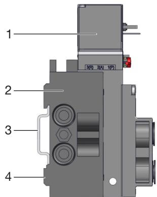
Secure the valve block directly against a panel backplate or mounting frame using M4 fasteners inserted through the lateral connection module mounting holes.
| Joint / Port Connection | Connection Thread / Type | Recommended Torque | Maximum Torque |
|---|---|---|---|
| Supply connection 1 (P), Exhaust 3 (R) | G 1/4 | 4.0 to 7.0 Nm | 20.0 Nm |
| Auxiliary ports / valve outlets | G 1/8 | 3.0 to 6.0 Nm | 7.0 Nm |
| Valve body to base module screws | 2x M2 / M3 fasteners | 0.6 ±0.1 Nm | 0.7 Nm |
| Cable plug Type 2516 fastening screw | Center screw Form C | 0.3 Nm | 1.0 Nm |
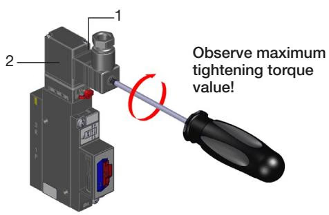
| Solenoid coil rotation screws | M2 coil fasteners | Step 1: 0.1 ±0.05 Nm Step 2: 0.2 ±0.05 Nm | 0.25 Nm |
Fastening Precautions
Do not use the solenoid coil as a lever arm when tightening threaded pneumatic fittings. Use appropriate open-ended wrenches on the provided module flats. Avoid pipe wrenches.
Valves arrive factory-assembled. If local cable routing requires an alternate connector exit angle, the coil can be rotated 180°:
Pneumatic lines must satisfy minimum mechanical requirements: hardness ≥ 40 Shore D (DIN 53505 / ISO 868), outer diameter to DIN 73378 (tolerance within ±0.1 mm), clean surface, cut square at 90°, and completely deburred.
| Hose Material | Tube Outer Diameter (OD) | Permitted OD Tolerance (ISO 14743:2020) |
|---|---|---|
| Polyamide (PA) | 3 mm to 10 mm | ±0.08 mm |
| Polyamide (PA) | 12 mm to 16 mm | ±0.10 mm |
| Polyurethane (PU) | 3 mm to 8 mm | ±0.10 mm |
| Polyurethane (PU) | 10 mm to 16 mm | ±0.15 mm |
| Hose Outer Diameter (OD) | 3 mm | 4 mm | 6 mm | 8 mm | 10 mm | 12 mm | 14 mm | 16 mm |
|---|---|---|---|---|---|---|---|---|
| Min. Tensile Force: Polyamide (PA) | 60 N | 70 N | 120 N | 170 N | 250 N | 300 N | 300 N | 350 N |
| Min. Tensile Force: Polyurethane (PU) | 25 N | 50 N | 100 N | 150 N | 200 N | 200 N | 250 N | 300 N |
Tubing Retention with Softer Hoses
When using flexible polyurethane (PU) tubing subject to temperature fluctuations or lateral pulling stress, insert internal support sleeves (ID 20099400) into tube ends prior to inserting into push-in collars.
BURKERT 378346 operates via individual single wiring. Each valve station is actuated independently through an industry-standard Type 2516 or Form C cable plug adhering to DIN EN 175301-803 (formerly DIN 43650 Form C).
| Test Parameter | Test Standard Limit |
|---|---|
| Ground Path Resistance | Maximum 0.1 Ω |
| Test Voltage | 12 V DC |
| Test Current | 1.0 A |
For bistable impulse coil configurations, observe strict polarity and minimum electrical pulse durations of 50 ms:
Before undertaking servicing, isolate electrical supplies, depressurize the pneumatic system, and exhaust line manifolds completely.
| Observed Fault | Potential Cause | Corrective Measure |
|---|---|---|
| Valves fail to switch | No operating voltage or voltage below lower limit | Verify 24 V DC supply and pin contact seating at Type 2516 plug. |
| Manual override locked in non-zero position | Return manual override detent to zero resting position. | |
| Supply pressure insufficient (< 2.0 bar) | Restore upstream compressor and regulator pressure to ≥ 2.0 bar. | |
| Delayed switching or continuous exhaust blow-off | Upstream line volume or flow restricted | Enlarge supply pipe diameter; check filter regulators and shut-off valves. |
| Block pressurized while valves energized | Depressurize system and apply pneumatic supply before energizing coils. | |
| Excessive back pressure from clogged silencers | Clean or replace exhaust silencer elements on port 3 (R). | |
| Contamination in pilot valve or pneumatic seat | Blow out internal galleries using clean pulsed air; replace pilot cartridge. | |
| Pneumatic leakage between modules | Damaged or missing O-rings at block interfaces | Disassemble module bay, renew O-rings (lubricated), and re-engage latches. |
| Leakage beneath valve body | Missing or improperly seated valve body flat seal | Check valve interface recess, verify 3 O-rings/profile seal, torque screws to 0.6 Nm. |
Explore similar products in our catalog


