

PN16

BURKERT 56632 is a Type 0256 direct-acting 2/2-way brass solenoid valve with G 3/8 ports, DN 4.0 mm orifice, NBR seal, and 120 V AC coil. Rated 0–12 bar for neutral fluids and technical vacuum with IP65 protection.
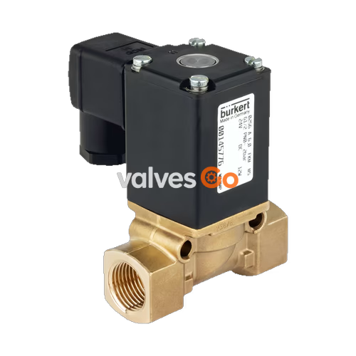
BURKERT 56632 (Type 0256) is a direct-acting, normally closed 2/2-way plunger solenoid valve designed for shut-off, dosing, and control of neutral fluids, gases, and technical vacuum. Constructed with an AF12 brass body featuring a 56 mm face-to-face length and G 3/8 internal threaded ports, this complete valve integrates a 4.0 mm orifice (DN 4.0) delivering a water flow factor Kv of 0.5 m³/h and a gas nominal flow rate QNn of 540 l/min. Actuation is driven by an epoxy-encapsulated Class H coil rated for 120 V AC, supporting 100% continuous duty rating (100% ED). The valve operates from 0 bar differential pressure up to 12 bar on liquids and 16 bar on gases, utilizing NBR seat seals across a medium temperature span of -10 °C to +90 °C and ambient temperatures up to +55 °C.
Circuit Function A (CF A)
Type 0256 in circuit function A is a direct-acting 2/2-way valve that remains closed when de-energized. Pressure is admitted above the seat at port 1 (P/NC). Energizing the coil lifts the plunger core directly against the return spring, opening the seat orifice without requiring differential pilot pressure.
| Technical Parameter | Specification Value |
|---|---|
| Valve Type | 0256 |
| Article Number (SKU) | 56632 |
| Circuit Function | Circuit function A (WW A / CF A), normally closed |
| Orifice Size | 4.0 mm (5/32") |
| Port Connection 1 & 2 | G 3/8 internal thread |
| Installation Length | 56 mm (short housing AF12) |
| Operating Pressure Range (AC Liquids) | 0.00 bar to 12.00 bar |
| Operating Pressure Range (AC Gases) | 0.00 bar to 16.00 bar |
| Flow Factor Kv (Water, +20 °C, 1 bar Δp) | 0.5 m³/h |
| Nominal Flow QNn (Gas) | 540 l/min |
| Nominal Operating Voltage | 120 V AC (50/60 Hz) |
| Voltage Tolerance | ±10% |
| Coil Duty Cycle | 100% ED continuous rating |
| AC Switching Time (Opening) | 10 ms to 20 ms (measured at +20 °C, 6 bar inlet pressure) |
| AC Switching Time (Closing) | 20 ms to 30 ms (measured at +20 °C, 6 bar inlet pressure) |
| Maximum Fluid Viscosity | 21 mm²/s (21 cSt) |
| Permissible Medium Temperature | -10 °C to +90 °C |
| Maximum Ambient Temperature | +55 °C |
| Storage Temperature | -40 °C to +80 °C |
| Degree of Protection | IP65 (with cable plug attached) |
| Electrical Connection Standard | Form A plug according to DIN EN 175301-803 |
| Coil Thermal Insulation Class | Class H (epoxy encapsulated) |
| Valve Body Material | Brass |
| Seat Seal Material | NBR (Nitrile rubber) |
| External Seal Material | NBR |
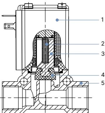
| Item No. | Component | Material Specification |
|---|---|---|
| 1 | Solenoid Coil | Epoxy (insulation class H) |
| 2 | Return Spring | Stainless steel 1.4310 |
| 3 | Plunger Core | Stainless steel 1.4105 |
| 4 | Seals (Seat and External) | NBR (Nitrile rubber) |
| 5 | Valve Body | Brass |
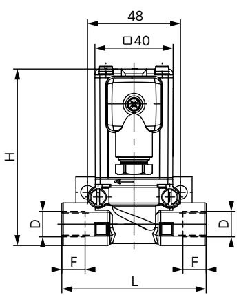
| Body Material | Thread Connection D | Thread Depth F [mm] | Total Height H [mm] | Face-to-Face Length L [mm] | Wrench Size SW [mm] |
|---|---|---|---|---|---|
| Brass (56632 AF12) | G 3/8 | 12 | 92 | 56 | 22 |
| Brass (AF12 alternative) | G 1/4 | 12 | 92 | 56 | 22 |
| Brass (standard body) | G 1/4 | 12 | 91 | 74.5 | 22 |
| Brass (standard body) | G 3/8 | 12 | 91 | 74.5 | 22 |
| Brass (standard body) | G 1/2 | 14 | 94 | 74.5 | 27 |
Pressure and High Voltage Hazards
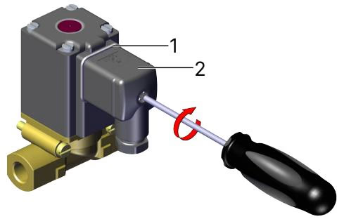
Protective Conductor and AC Solenoids
Operational Readiness Recommendation
During prolonged system downtime under continuous energization or extended standby, actuate at least 1 to 2 switching cycles per day to prevent the plunger core and seal from sticking.
Authorized Maintenance Only
Maintenance work must be conducted exclusively by authorized technical personnel using appropriate tools. Ensure complete de-energization and depressurization before opening the valve body.
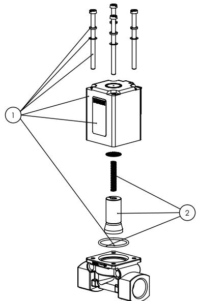
Spare part sets for Burkert Type 0256:
| Accessory Description | Specification / Details | Article Number |
|---|---|---|
| Mounting Set for Brass Body | Mounting clamp with 2 cheese head screws M5×35 (37 mm threaded hole spacing, 48 mm clamp bore spacing) | 151287 |
| Cable Plug Type 2518 Form A | Without circuitry, 0–250 V AC/DC | 314802 |
| Cable Plug Type 2518 Form A | With LED, 12–24 V AC/DC | 314812 |
| Cable Plug Type 2518 Form A | With LED and varistor, 12–24 V AC/DC | 314820 |
| Plug-in Timer Type 1087 Form A | Analogue timer, 24–240 V AC/DC | 348829 |
| Plug-in Timer Type 1087 Form A | Digital timer, 110–240 V AC/DC | 348831 |
Explore similar products in our catalog


