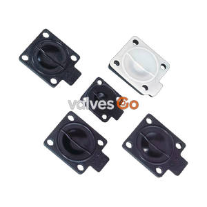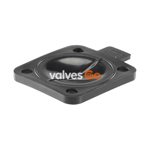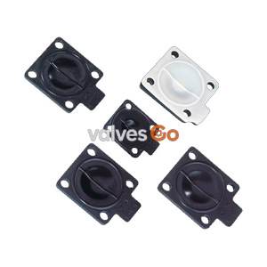
Size 15

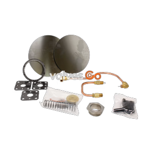
Complete maintenance kit for Spirax Sarco FTS14 austenitic stainless steel ball float steam traps. Includes float, air vent, seats, gaskets, and screws.
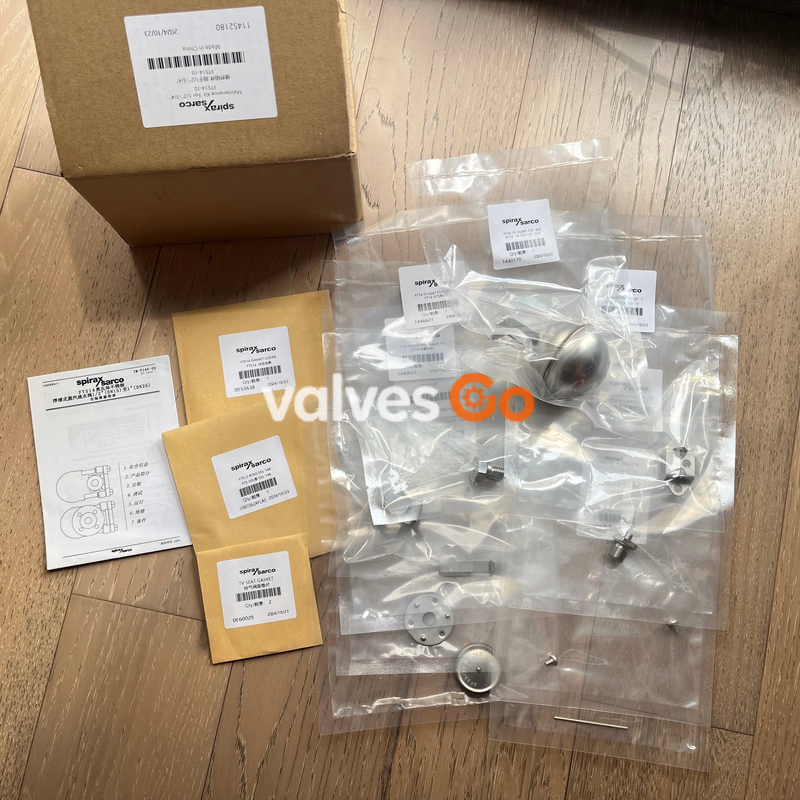
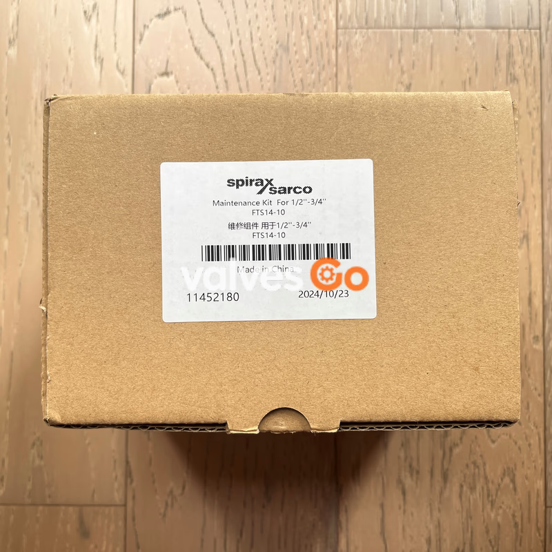
The Spirax Sarco FTS14 maintenance kit provides all necessary replacement components to fully service the FTS14 austenitic stainless steel ball float steam trap. This comprehensive kit ensures the continued efficient condensate drainage and prompt air removal of the host trap. It is compatible with FTS14 traps in sizes ½" (DN15) to 1" (DN25) across pressure ranges of 4.5, 10, and 14 bar.
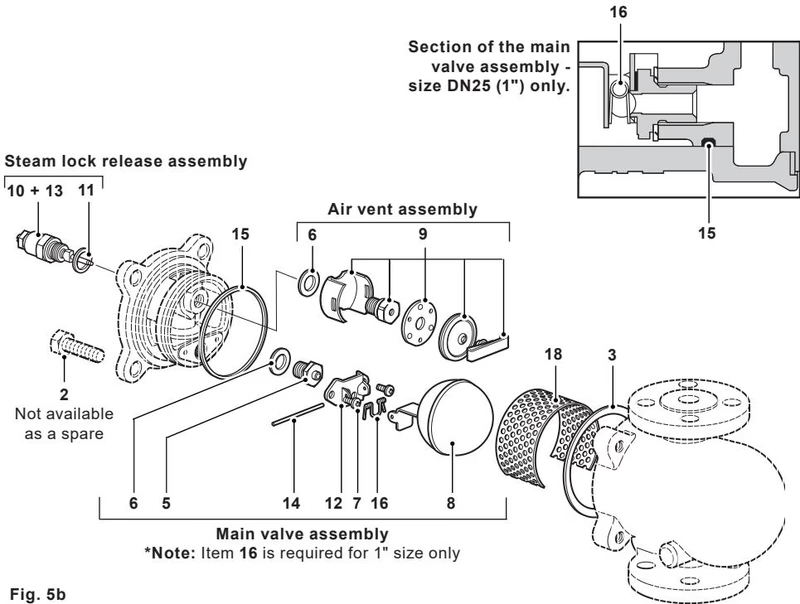
The maintenance kit includes the following replacement parts to restore the trap to optimal working condition:
| Item No. | Part Description | Material |
|---|---|---|
| 3 | Cover gasket | Reinforced exfoliated graphite |
| 5 | Main valve seat | Stainless steel (BS 970 431 S29) |
| 6 | Main valve/air vent seat gasket (2 off) | Stainless steel |
| 7 | Main valve assembly screws (2 off) | Stainless steel |
| 8 | Ball float and lever | Stainless steel (BS 1449 304 S16) |
| 9 | Air vent assembly | Stainless steel |
| 12 | Pivot frame | Stainless steel |
| 14 | Pivot | Stainless steel |
| 15 | 'O' ring | Grey Viton (FDA approved) |
| 16 | Valve spring (1" only) | Stainless steel |
| 18 | Strainer screen | Stainless steel (optional extra) |
Always order spares by using the description "Maintenance kit" and state the size, type of trap, and pressure range (i.e., 4.5, 10, or 14 bar).
Ordering Example
1 - Maintenance kit for a Spirax Sarco ½" FTS14-4.5 steam trap.
Before undertaking any maintenance on the trap, it must be isolated from both the supply line and return line, and any pressure allowed to safely normalise to atmosphere. The trap should then be allowed to cool. When reassembling, ensure that all joint faces are clean.
WARNING
The cover gasket contains a thin stainless steel support ring which may cause physical injury if not handled and disposed of carefully.
| Item | Part | Tool / Size | Torque (N m) |
|---|---|---|---|
| 5 | Main valve seat | 17 A/F | 50 - 55 |
| 7 | Main valve assembly screws | Pozidrive M4 x 6 | 2.5 - 3.0 |
| 9 | Air vent assembly | 17 A/F | 50 - 55 |
Explore similar products in our catalog