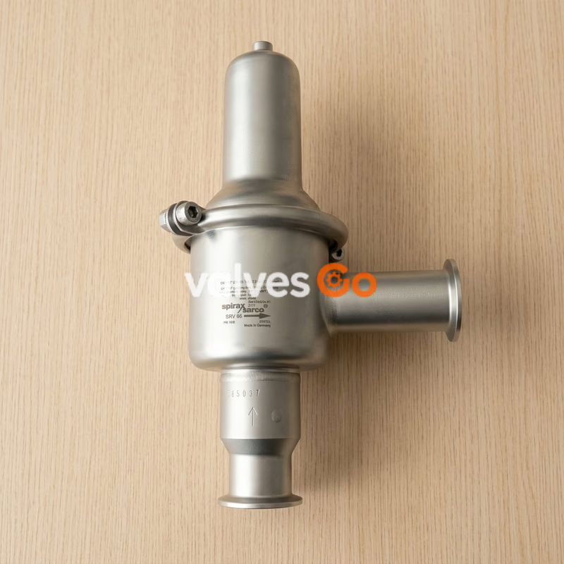


PN25

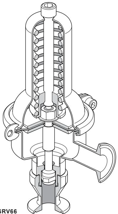
Spirax Sarco srv66 is an angle pattern self-draining sanitary pressure regulating valve of all 316 type stainless steel construction suitable for use on steam, water and inert industrial gases.
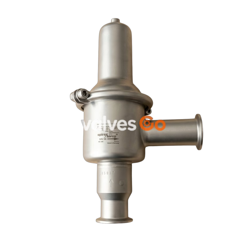
Spirax Sarco srv66 is an angle pattern self-draining sanitary pressure regulating valve of all 316 type stainless steel construction suitable for use on steam, water and inert industrial gases. It is available with sanitary clamp compatible connections, requires no external pressure sensing line and has clean in place (CIP) and sterilise in place (SIP) capability.
Typical applications include: Clean steam, gas and liquid supplies to bioreactors, centrifuges, freeze dryers, sterilisers, autoclaves, process tanks, humidifiers and culinary equipment.
Valve tightness is in accordance with VDI / VDE guideline 2174 (leakage rate < 0.5% of Kvs value).
| Body design conditions Inlet | PN10 |
|---|---|
| Outlet | see 'Pressure setting range' below |
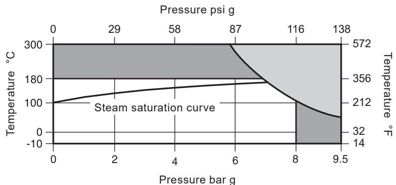
| Maximum design pressure | 9.5 bar @ 50 C (138 psi g @ 122 °F) |
| Maximum design temperature | 300 °C @ 5.8 bar (572 °F @ 84 psi g) |
| Minimum design temperature | -10°C(14°F) |
| Maximum operating temperature | 180°C(356°F) |
| Maximum operating pressure (inlet) | 8 bar g (116 psi g) |
| Minimum operating temperature | -10°C(14°F) |
| Designed for a maximum cold hydraulic test pressure of | 15.2 bar g (220 psi g) |
| Size | DN15 - DN50 ( - 2") | ||
|---|---|---|---|
| Inlet/outlet rating | PN10/PN2.5 | PN10/PN6 | PN10/PN10 |
| Spring range | 0.3- 1.1 bar g (4.4 - 16.0 psi g) | 0.8-2.5 bar g (11.6 - 36.3 psi g) | 1.0 -5.0 bar g (14.5 - 72.5 psi g) |
Maximum permitted outlet pressure = 1.5 times set pressure
| No. | Part | Material | |
|---|---|---|---|
| 1 | Body (integral seat) | Stainless steel | 1.4404 (316L) |
| 2 | Main valve | Stainless steel | 1.4404 (316L) |
| 3 | Spring housing | Stainless steel | 1.4404 (316L) |
| 4 | Adjustment screw | Stainless steel | BS 6105 A4 70 |
| 5 | Spring | Stainless steel | 1.4301 (304) |
| 6 | Spring clip (not listed) | Stainless steel | 1.4301 (304) |
| 7 | Diaphragm nut | Stainless steel | BS 6105 A4 70 |
| 8 | Diaphragm plate | Stainless steel | 1.4404 (316L) |
| 9 | 'V' band clamp | Stainless steel | 1.4404 (316L) |
| 10 | Diaphragm | FPM (Viton)/ PTFE | |
| 11 | O'ring | PTFE | |
| 12 | 'V' band clamp screw | Stainless steel | BS 6105 A4 70 |
| Setting bar range | Size | Nominal diameter DN | |||||
|---|---|---|---|---|---|---|---|
| 15 | 20 | 25 | 32 | 40 | 50 | ||
| 0.8 - 2.5 / 1-5 | AE1 | 90 | 90 | 90 | 120 | 120 | 120 |
| AE2 | 90/100/110 | 90/100/110 | 90 | 120 | 120 | 120 | |
| C | 200 | 200 | 200 | 200 | 200 | 200 | |
| D | 138 | 138 | 138 | 138 | 138 | 138 | |
| 0.3 - 1.1 | AE1 | 120 | 120 | 120 | 120 | 120 | 120 |
| AE2 | 120/140 | 120/140 | 120 | 120 | 120 | 120 | |
| C | 200 | 200 | 200 | 200 | 200 | 200 | |
| D | 200 | 200 | 200 | 200 | 200 | 200 |
To maximise the control accuracy (especially for large load variations) use the Kv values given at 20% offset. For safety valve sizing use the maximum Kv values.
| Valve size | DN15 | DN20 | DN25 | DN32 | DN40 | DN50 |
|---|---|---|---|---|---|---|
| Kv at 20% offset | 2.0 | 3.0 | 3.5 | 4.0 | 4.5 | 5.2 |
| Maximum Kv | 2.6 | 3.9 | 4.6 | 5.2 | 5.9 | 6.8 |
For conversions: CV (UK) = KV x 0.963, CV (US) = KV x 1.156
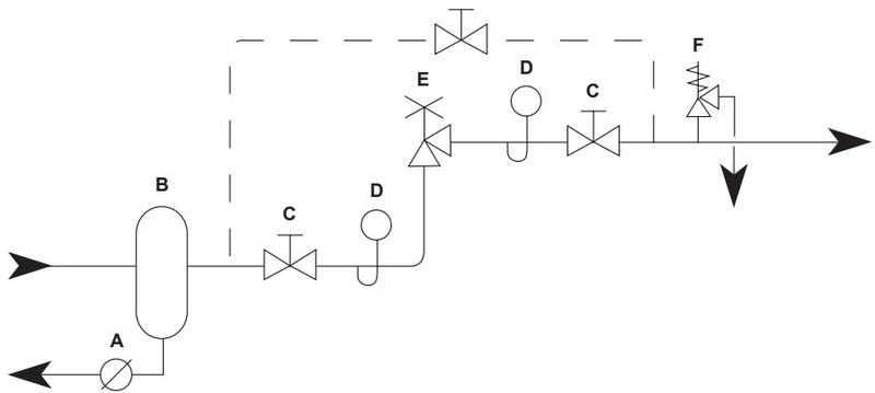
Before installing the valve thoroughly flush the pipeline. Ideally the valve should be installed in a pressure reducing valve station, at the very minimum there should be a separator and strainer fitted upstream, these should be serviced at regular intervals. The SRV66 should always be fitted with the inlet horizontal and the spring housing directly above the valve. Most applications will require a safety valve to be installed downstream in case of accidental overpressure. It should be noted that the valve should not be used as a shut-off valve, a separate valve should therefore be used for isolation purposes if required.
The pressure reducing valve should not be insulated as this may lead to over heating and destroy the elastomer seals.
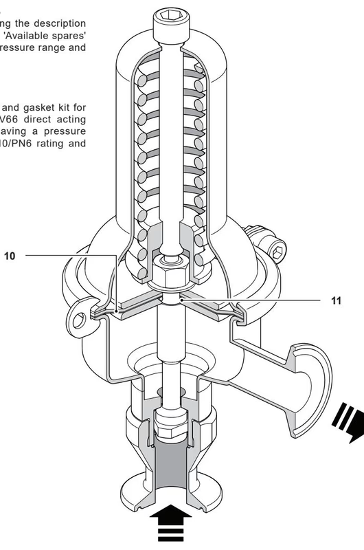
Diaphragm and 'O' ring gasket kit.
Explore similar products in our catalog




