


PN25

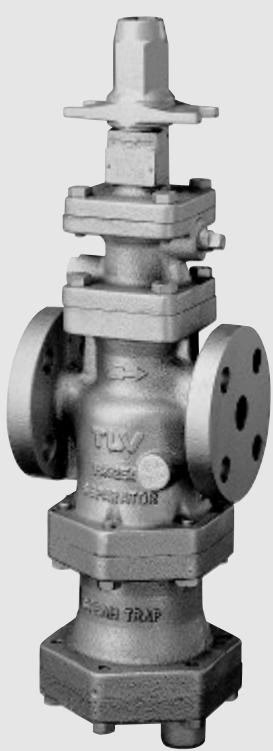
TLV A-COS-10 self-actuated pressure reducing valve for air featuring a shock-absorbing piston, built-in cyclone separator, and free float air trap.
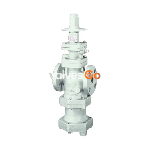
The TLV A-COS-10 is a technologically advanced self-actuated pressure reducing valve for air, combined with a condensate separator and an air trap. This integrated design provides accurate control and air conditioning to maximize process system performance while supplying dry, high-quality air.
Using air in which matter such as condensate, scale, or types of oil is entrained can not only result in problems with the air-using equipment and lowered productivity, but can also lead to shortened service life and malfunction of reducing valves. The A-COS-10 eliminates these problems and makes possible the supply of high-quality air at a constant pressure.
| Model | ACOS-10 |
|---|---|
| Body Material | Ductile Cast Iron (GGG40.3/EN 5.3103) / Cast Stainless Steel (A351/A351M Gr.CF8 or CF8M) |
| Connection | Flanged, DIN |
| Size | DN 15, 20, 25, 40, 50 |
| Maximum Operating Pressure (PMO) | 9 barg |
| Maximum Operating Temperature (TMO) | 100 °C |
| Primary Pressure Range | 1 – 9 barg |
| Adjustable Pressure Range | 0.5 – 7 barg |
| Minimum Differential Pressure | 0.5 bar |
| Minimum Adjustable Flow Rate | 10% of rated flow rate |
| Applicable Fluid | Air |
WARNING
Do not use for toxic, flammable, or otherwise hazardous fluids. DO NOT use this product in excess of the maximum operating pressure differential. Such use could make discharge impossible (blocked).
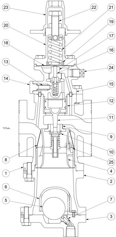
| No. | Name | No. | Name |
|---|---|---|---|
| 1 | Main Body | 14 | Pilot Screen Holder |
| 2 | Separator Body | 15 | Pilot Body |
| 3 | Trap Cover | 16 | Pilot Valve |
| 4 | Separator | 17 | Pilot Valve Seat |
| 5 | Float | 18 | Diaphragm |
| 6 | Float Cover | 19 | Diaphragm Support |
| 7 | Trap Valve Seat | 20 | Spring Housing |
| 8 | Separator Screen | 21 | Coil Spring |
| 9 | Main Valve Seat | 22 | Adjustment Screw |
| 10 | Main Valve | 23 | Spanner Cap |
| 11 | Piston | 24 | Plug – Sensing Line Port |
| 12 | Cylinder | 25 | Plug (option) |
| 13 | Pilot Screen |
In order to ensure stable air flow, the piping upstream and downstream of the product must be straight runs. If the product is installed either directly before or after an elbow or control valve, unevenness in air flow may result in chattering and unstable pressure.
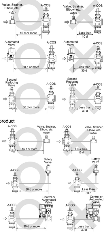
Inlet (primary side):
Outlet (secondary side):
(Note: d = pipe diameter)
Make sure the product is installed on horizontal piping, so that the arrow mark on the body matches the direction of air flow and the adjustment section faces up. Allowable inclination is 10 degrees in the fore-aft direction and 15 degrees in the plane perpendicular to the air flow line.
Before installing the product, be sure to blow down all piping thoroughly. Blowdown is especially important for newly installed piping or after the system has been shut down for a long period of time.
To ensure long service life, the following inspection and maintenance is recommended to be performed regularly:
| Part | Inspection and Maintenance Frequency |
|---|---|
| Screens (Separator and Pilot) | Disassemble and clean annually. If there is substantial blockage, install a strainer (approx. 60 mesh) ahead of the product. |
| Main Valve, Main Valve Seat, Pilot Valve, Pilot Valve Seat | Replace after approximately 15,000 hours. If there is chattering or dirt, premature wear may result. |
| Piston Ring | Replace after approximately 8,000 hours. If there is chattering or if scale build-up is severe, premature wear may result. |
| Piston | Replace after approximately 30,000 hours. If hunting or chattering takes place, premature wear may result. |
| Trap Valve Seat | Replace after approximately 40,000 hours. If scale build-up is severe, blockage may occur in a short period of time. |
| Diaphragm | Replace after approximately 30,000 hours. If hunting or chattering takes place, cracks or fatigue may develop in a short period of time. |
It is a recommended practice to dismantle and inspect the product once a year for preventive maintenance purposes.
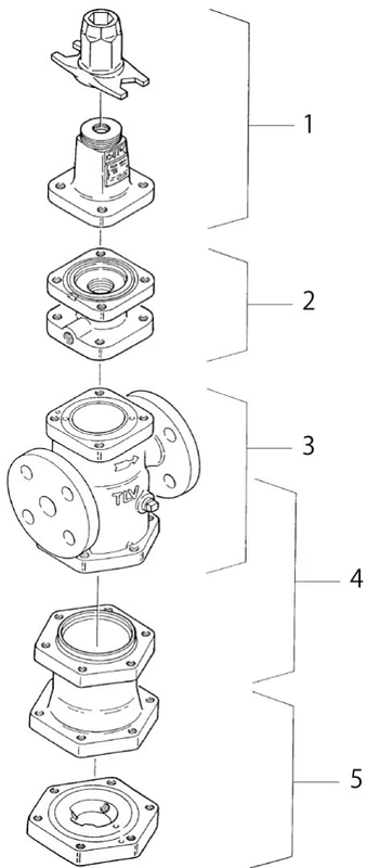
Assemble the unit using the same procedure in reverse order. Apply anti-seize to the threaded portion of screws and bolts. Fasten the bolts one at a time in an alternating diagonal pattern to provide uniform seating.
| Problem | Symptom | Cause | Remedy |
|---|---|---|---|
| The secondary pressure does not rise | The pressure does not increase | No air is being supplied or the inlet valve is closed | Check the valves and piping at the primary side |
| The entrance to the screens or strainer is clogged | Clean or blow down | ||
| The secondary pressure cannot be adjusted or increases abnormally | Adjustment is difficult, and set pressure varies | The pilot screen is clogged | Clean |
| There is insufficient air flow | Check the flow, replace the product if necessary | ||
| The piston is clogged with dirt | Clean, check the piston ring | ||
| The piston ring is worn | Replace with a new piston ring | ||
| There is a build-up of dirt on the sliding surfaces | Clean | ||
| The adjustment screw has seized | Replace with a new adjustment screw | ||
| The small hole on the piston is clogged | Clean | ||
| The diaphragm is distorted or damaged | Replace with a new diaphragm | ||
| Upon closing the valves on the secondary side, the secondary pressure abruptly rises | The bypass valve is leaking | Check, clean, and replace with a new valve if necessary | |
| There is a build-up of dirt on or damage to the pilot valve seat or main valve seat | Clean, align, replace if necessary | ||
| Hunting or chattering occurs | Occurs at low air demand | It is being operated below the lower flow rate limit | Check the volume of air supply, replace with a smaller diameter valve |
| Hunting never stops | There is too high a reduction ratio | Change to an acceptable operating range | |
| Chattering never stops | Condensate is contained, or the trap is blocked | Check the trap, check the piping | |
| Abnormal noises | Makes a high-pitched noise | There is too high a reduction ratio / The flow is too great | Use two-stage reduction, check the flow rate and use a larger size valve |
| Faulty air trap | Air is blowing | There is a build-up of dirt on the trap valve seat or at the float base | Clean |
| The float is deformed | Check for water hammer, replace with a new float | ||
| No condensate is discharged | The primary pressure exceeds the trap valve seat maximum working pressure | Adjust primary pressure | |
| Water is inside the float | Replace with a new float | ||
| The trap valve seat is clogged | Clean, replace with a new trap valve seat |
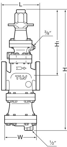
ACOS-10 Flanged (DIN2501 PN25/40)
| DN | L (mm) | H (mm) | H1 (mm) | W (mm) | Weight (kg) |
|---|---|---|---|---|---|
| 15 | 150 | 495 | 285 | 105 | 15 |
| 20 | 150 | 495 | 285 | 105 | 15 |
| 25 | 160 | 522 | 282 | 150 | 20 |
| 40 | 200 | 572 | 302 | 165 | 27 |
| 50 | 230 | 635 | 315 | 195 | 44 |
(Weight is for ductile cast iron. Flange to flange dimension of DN 15 is not according to DIN standard, due to size of separator and steam trap.)
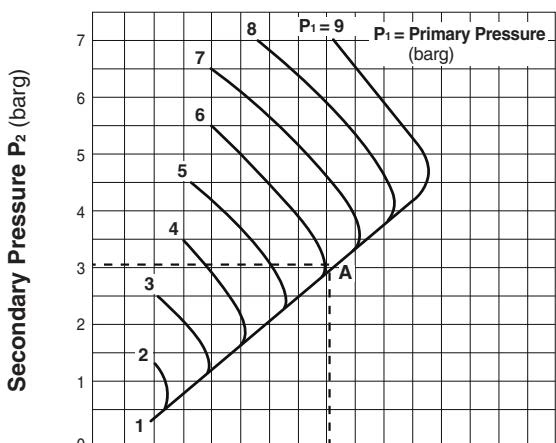
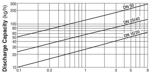
Rated flow rates represent equivalent flow rates of air at 20°C under atmospheric pressure.
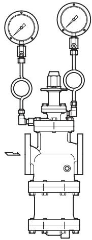
| No. | Part Name | No. | Part Name |
|---|---|---|---|
| 1 | Valve Body | 5 | Siphon Tube* |
| 2 | Holder Plug | 6 | Dampener* |
| 3 | Holder Plug Gasket | 7 | Dampener Gasket* |
| 4 | Elbow (male/female)* | 8 | Pressure Gauge* |
(Parts marked with * must be purchased separately. A pressure gauge unit option is available to replace the standard screen holder plug.)
Explore similar products in our catalog




