



Skip to content
Stainless SteelDirect-ActingSoft SeatAir

TLV A-DR20 Direct-Acting Pressure Reducing Valve for Air

TLV A-DR20 direct-acting pressure reducing valve for air. Compact stainless steel construction with soft seat (fluorine rubber). Adjustable pressure up to 0.9 MPaG.
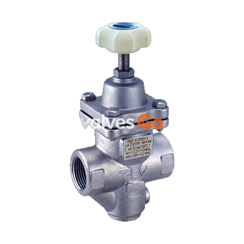
TLV A-DR20 Direct-Acting Pressure Reducing Valve for Air

TLV A-DR20 is a compact stainless steel direct-acting pressure reducing valve with a soft seat (fluorine rubber) designed specifically for air applications. It is capable of reducing primary pressures between 0.2 and 1.0 MPaG to secondary pressures between 0.014 and 0.9 MPaG. Constructed for a long service life, its stainless steel body offers superior durability. The shared manual also covers the related DR20 model for steam and air applications.
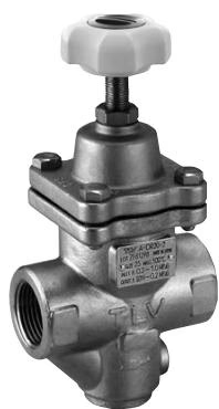
TLV A-DR20 exterior view

Safety Considerations

WARNING

  • Install properly and DO NOT use outside the recommended specification ranges.
  • Take measures to prevent people from coming into direct contact with product outlets.
  • Wait until internal pressure equals atmospheric pressure and the surface has cooled before disassembling.
  • Use only recommended components when repairing.
  • Do not use excessive force when connecting threaded pipes.
  • Use only under conditions in which no freeze-up will occur.
  • Use under conditions in which no water hammer will occur.

Configuration

For the A-DR20, the seating area uses a soft seat (fluorine rubber), which is inlaid in the main valve.
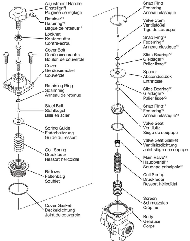
TLV A-DR20 exploded view

Specifications

ModelA-DR20-2A-DR20-6A-DR20-10
Primary Pressure Range0.2 – 1.0 MPaG0.2 – 1.0 MPaG0.6 – 1.0 MPaG
Adjustable Pressure Range*0.014** – 0.2 MPaG0.18 – 0.6 MPaG0.54 – 0.9 MPaG
Minimum Adjustable Flow RateAir: 5% of rated flow rateAir: 5% of rated flow rateAir: 5% of rated flow rate

* Secondary pressure must not exceed 90% of primary pressure.** But not less than 1/30 of primary pressure.

Piping and Installation

INFO

Installation, inspection, maintenance, repairs, disassembly, adjustment and valve opening/closing should be carried out only by trained maintenance personnel.

If a pressure reducing valve is installed directly before or after an elbow or control valve, unevenness in flow may result in chattering and unstable pressure. Install the valve on straight runs of piping:
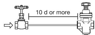
  • Maintain a straight run of 10 d or more when a manual valve or strainer is installed at the inlet.
  • Maintain a straight run of 30 d or more when an automated valve is installed at the inlet.
  • Maintain a straight run of 15 d or more when a manual valve is installed at the outlet.

TLV A-DR20 straight piping run for manual valve

Installing Valves

ON/OFF Valve: Install any required on-off valve on the inlet side of the A-DR20 to avoid chattering and potential damage. Control Valve and Safety Valve: A control valve installed downstream may raise pressure between the A-DR20 and the control valve when closed. Install the control valve close to the equipment and install a safety valve downstream of the control valve.
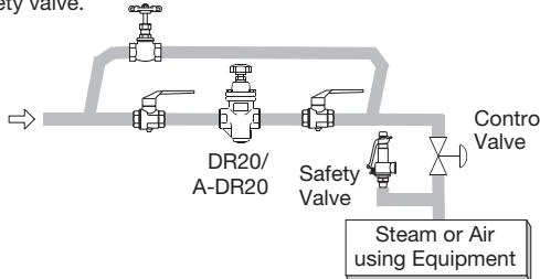
TLV A-DR20 control valve and safety valve installation

Tolerance Angle

Ensure the A-DR20 is installed on horizontal piping with the adjustment handle facing up. The raised TLV lettering should be horizontal with the arrow pointing in the flow direction. Allowable inclination is 10° front-to-back and 15° horizontally.
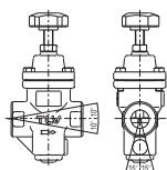
TLV A-DR20 tolerance angle for installation

Piping Supports and Size

Support inlet and outlet pipes securely to avoid excessive load, bending, and vibration. If secondary flow velocity exceeds 30 m/s, install a diffuser.

Two-Stage Pressure Reduction

Employ 2-stage pressure reduction if the required reduction is not possible with a single valve.

TLV A-DR20 two-stage pressure reduction

Accessories

Install a shut-off valve and pressure gauge at both the inlet and outlet, and a shut-off valve in the bypass line. Ball valves are recommended for shut-off valves.
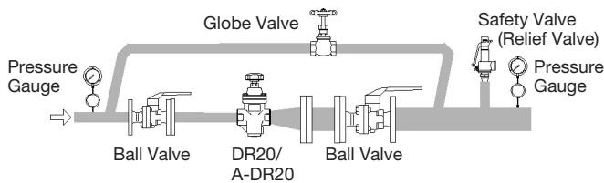
TLV A-DR20 accessories installation

Adjustment

  1. Blow down all pipe lines thoroughly.
  2. Ensure shut-off and bypass valves are completely closed.
  3. Loosen the locknut and turn the adjustment handle counter-clockwise to free the coil spring.
  4. Slowly and fully open the inlet shut-off valve.
  5. Slightly open the outlet shut-off valve.
  6. Turn the adjustment handle clockwise until the desired outlet pressure is obtained, then wait several minutes.
  7. Slowly and fully open the outlet shut-off valve.
  8. Retighten the locknut.
  9. When shutting down, always close the outlet valve first, then the inlet valve.

Inspection and Maintenance

Regular inspection and maintenance should be performed at least once a year.

  • Body, Cover: Check inside for damage, dirt, grease, oil film, rust or scale.
  • Screen: Check for clogging, damage or deformation.
  • Valve and Seat: Check for rust, scale, oil film, wear or damage. (Note: For A-DR20, the rubber is inlaid in the main valve and cannot be removed; the main valve itself must be replaced.)
  • Valve Stem: Check for wear or damage.
  • Bellows: Check for cracks, damage or deformation.
  • Gaskets: Check for warping or damage.

Reassembly Precautions

  • PTFE gaskets may be re-used if free from fault, crushing, or deformation.
  • Apply anti-seize to the steel ball and threaded portions. Apply a small amount to valve seat threads without contacting other parts.
  • Fasten bolts diagonally and alternately. Tightening torque for the cover bolt is 25 N·m, and for the valve seat is 120 N·m.
  • Make sure the valve stem operates smoothly without binding after assembly.

Troubleshooting

  • Secondary pressure does not increase: Check for closed valves, clogged screens, or excessive flow rate/pressure range mismatch.
  • Adjustment is difficult / Set pressure varies: Check if flow rate is too low, primary pressure fluctuates, valve stem buildup is present, or flow rate fluctuation is too large.
  • Secondary pressure abruptly rises upon closing secondary valves: The adjustment handle may be seized, holes in the spacer clogged, or the slide bearing/bellows distorted or damaged.




