PN25

TLV BD800 Bypass Blow Valve with scale removal function for high temperature and pressure steam trap bypass lines. Max pressure 6.5 MPaG, max temperature 425 °C.
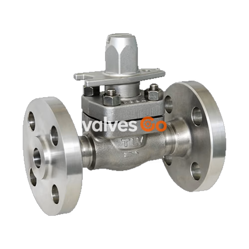
TLV BD800 is a bypass blow valve with a scale removal function and inline maintainability for long service life. It is designed for use in high temperature and high pressure applications, making it ideal for installation on steam trap bypass lines. The proven special material combined with a unique cleaning mechanism reduces the burden of valve maintenance and operation.
| Model | BD800 |
|---|---|
| Connection | Screwed, Socket Welded, Flanged |
| Size (mm) | 15, 20, 25 |
| Maximum Operating Pressure (PMO) | 6.5 MPaG |
| Maximum Operating Temperature (TMO) | 425 °C |
| Applicable Standards | API 598, ASME B16.34 |
| Seat Leakage (Gas test in accordance with API 598) | 0 bubbles / 15 seconds @ 0.6 MPaG |
| Applicable Fluids | Steam, Water, Air |
WARNING
Do not use for toxic, flammable or otherwise hazardous fluids. PRESSURE SHELL DESIGN CONDITIONS (NOT OPERATING CONDITIONS): Maximum Allowable Pressure (MPaG) PMA: 6.5; Maximum Allowable Temperature (°C) TMA: 425. To avoid abnormal operation, accidents or serious injury, DO NOT use this product outside of the specification range. Local regulations may restrict the use of this product to below the conditions quoted.
| No. | Description | Material | JIS | ASTM/AISI |
|---|---|---|---|---|
| 1 | Body | Stainless Steel | — | A182 Gr.F304 |
| 2 | Bonnet | Carbon Steel | — | A105 |
| 3 | Valve Seat | — | — | — |
| 4 | Valve Seat Gasket | Stainless Steel | SUS316L | AISI316L |
| 5 | Bonnet Gasket | Graphite/Stainless Steel | - / SUS304 | - / AISI304 |
| 6 | Valve Stem | — | — | — |
| 7 | Gland Packing | Graphite | — | — |
| 8 | Gland Retainer | Stainless Steel | SUS303 | AISI303 |
| 9 | Spanner Cap | Cast Stainless Steel | — | A351 Gr.CF8 |
| 10 | Bonnet Bolt | Stainless Steel | — | A193 Gr.B8 Cl.2 |
| 11 | Bonnet Nut | Stainless Steel | — | A194 Gr.8 |
| 12 | Flange | Cast Stainless Steel | — | A351 Gr.CF8 |
| 13 | Nameplate | Stainless Steel | SUS304 | AISI304 |
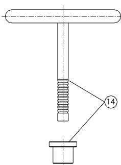
| 14 | Gland Packing Removal Tool | Stainless Steel | — | — |
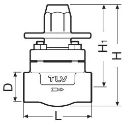
| Size (mm) | L | H | H1 | Ø D | Weight (kg) |
|---|---|---|---|---|---|
| 15 | 80 | 140 | 115 | 40 | 2.2 |
| 20 | 92 | 140 | 115 | 40 | 2.5 |
| 25 | 160 | 140 | 115 | 50 | 3.0 |
Rc(PT), other standards available
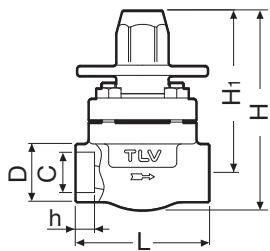
| Size (mm) | L | H | H1 | Ø D | Ø C | h | Weight (kg) |
|---|---|---|---|---|---|---|---|
| 15 | 80 | 140 | 115 | 32 | 22.2 | 11 | 2.2 |
| 20 | 92 | 140 | 115 | 38 | 27.7 | 13 | 2.5 |
| 25 | 160 | 140 | 115 | 48 | 34.5 | 14 | 3.0 |
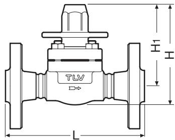
| Size (mm) | L (ASME 150RF) | L (ASME 300RF) | L (ASME 600RF) | H | H1 | Weight (kg)* |
|---|---|---|---|---|---|---|
| 15 | 152 | 152 | 165 | 140 | 115 | 4.1 |
| 20 | 178 | 178 | 190 | 140 | 115 | 5.4 |
| 25 | 203 | 203 | 216 | 140 | 115 | 6.5 |
Other standards available, but length and weight may vary. Weight is for Class 600RF.
| Nominal Valve Size (mm) | 15 | 20 | 25 |
|---|---|---|---|
| Cv (US) | 3.5 | 3.5 | 3.5 |
| Cv (UK) | 2.9 | 2.9 | 2.9 |
| Kvs (DIN) | 3.0 | 3.0 | 3.0 |
WARNING
Take measures to prevent people from coming into direct contact with product outlets. Failure to do so may result in burns or other injury from the discharge of fluids.
INFO
Before using the product, ensure piping is cleaned and flushed to remove foreign matter. Failure to observe this precaution may cause leakage from the valve seat. Do not use excessive force when connecting threaded pipes to the product. Over-tightening may cause breakage leading to fluid discharge.
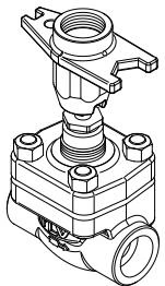
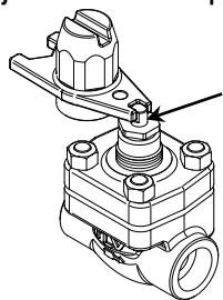
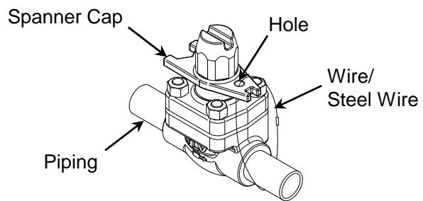
A hole in the spanner cap allows it to be fixed by passing a wire and tightening it around the piping or flange. Restricting movement of the spanner cap prevents the valve from being operated erroneously.
Relation between CV / Kvs Values and No. of Turns of the Valve Stem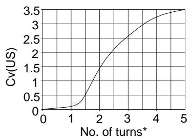
WARNING
When using the spanner cap, be sure to use heat-resistant gloves. Disassembling or removing the product when it is hot or under pressure may lead to discharge of fluids, causing burns, other injuries or damage.
When fluid leaks from the gland section, retighten the gland holder. Make sure that the valve is in the fully closed position.
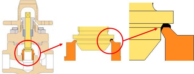
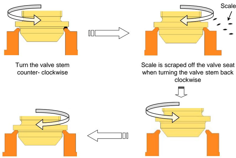
When scale adheres to the valve seat section, sealing is inhibited, causing fluid leakage. Restore sealing performance by following these steps:
| Part Name | Torque (N·m) | Distance Across Flats (mm) |
|---|---|---|
| Bonnet Nut | 80 | 17 |
| Gland Holder | 60 | 22 |
| Valve Seat | 80 | 21 |
(Coat all threaded portions with anti-seize.)
| Problem | Cause | Remedy |
|---|---|---|
| Fluid is leaking from the outlet (even) when the valve is closed | The valve stem is not tightened sufficiently | Place the spanner on the flat surfaces of the valve stem and tighten to the proper torque (16 N·m). Tighten the spanner cap to the proper torque (16 N·m). |
| The sealing surfaces of the valve seat and valve stem are damaged or clogged with rust and scale | Clean the valve seat and valve stem; if leakage does not stop, replace with a new valve seat and/or valve stem | |
| Fluid is leaking from the gland section | The gland holder is loosened | Retighten the gland holder, clean or replace with new parts |
| The valve stem does not move | The valve stem is clogged with rust and scale | Clean or replace with a new valve stem |
| Fluid is leaking from a place other than the outlet | Fluid is leaking from between the bonnet and body; Gasket deterioration or damage; Sealing surfaces are damaged or clogged | Replace with new gasket(s) |
| Improper tightening torques were used | Tighten to the proper torque | |
| The valve stem and the valve seat frequently become damaged | Water hammer has occurred | Check if the valve stem is over-tightened; replace if deteriorated. Check and correct the piping |
Explore similar products in our catalog