Up to 99.8% Efficiency

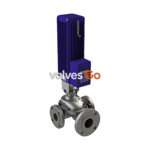
TLV CT16 compact multi-purpose electro-pneumatic control valve with digital I/P positioner. Features ductile cast iron or stainless steel body and drain plug.
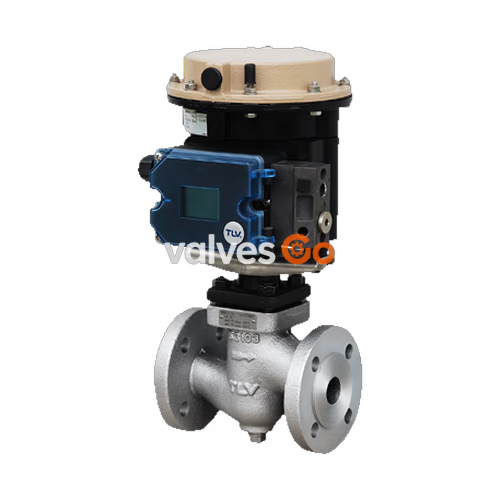
The TLV CT16 is a compact multi-purpose electro-pneumatic globe control valve equipped with a digital I/P positioner and a drain plug. Designed for steam, water, air, and other non-hazardous fluids, it features a highly efficient multi-spring actuator with a low overall height that facilitates compact installation. The self-adjusting positioner ensures tight shut-off and improves control during low flow via auto-tuning zero calibration.
WARNING
Do not use with toxic, flammable or otherwise hazardous fluids. Install properly and DO NOT use this product outside the recommended operating pressure, temperature and other specification ranges.
Valve Section
| Specification | Ductile Cast Iron (EN 5.3103) | Cast Stainless Steel (A351 Gr.CF8M) |
|---|---|---|
| Connection | Flanged PN25 DIN EN 1092-2 | Flanged PN40 DIN EN 1092-2 |
| Size (DN) | 15, 20, 25, 32, 40, 50 | 15, 20, 25, 32, 40, 50 |
| Max. Operating Pressure (PMO) | Up to 22 barg (varies by size) | Up to 32 barg (varies by size) |
| Max. Operating Temperature (TMO) | 220 °C | 220 °C |
| Leak Rate Class | Class IV / Metal sealing | Class IV / Metal sealing |
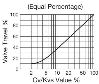
| Characteristic | Equal percentage | Equal percentage |
| Rangeability | 50:1 | 50:1 |
Actuator / Positioner Section
| Specification | Value |
|---|---|
| Fail-safe Position | Valve CLOSED (Air to Open) |
| Motive Medium | Oil-free air, filtered to 5 μm |
| Electrical Input Signal | 4 to 20 mA |
| Load Impedance | Max. 6.3 V |
| Air Supply Pressure Range | 3.7 to 6 barg |
| Ambient Temperature Range | -25 to +80 °C |
| Protection Class | IP 66 |
| Intrinsically Safe Rating (optional) | ATEX II 2G Ex i a IIC T4 |

| No. | Description | Material |
|---|---|---|
| 1 | Valve Body | Ductile Cast Iron / Cast Stainless Steel |
| 2 | Valve Seat | Stainless Steel X8CrNiS18-9 |
| 3 | Plug and Stem | Stainless Steel X8CrNiS18-9 |
| 4 | Valve Bonnet Gasket | Graphite |
| 5 | Valve Bonnet | Carbon Steel A105 / Stainless Steel SUS316Ti |
| 6 | Flange | Carbon Steel A105 |
| 7 | Stuffing Box V-ring Packing | Fluorine Resin PTFE with Carbon |
| 8 | Positioner Housing | Polyphthalamide PPA |
| 9 | Positioner Cover | Polycarbonate PC |
| 10 | Actuator Body | Aluminium GD-Al Si 12 |
| 11 | Drain Plug | Carbon Steel |
| 12 | Silencer | Stainless Steel |
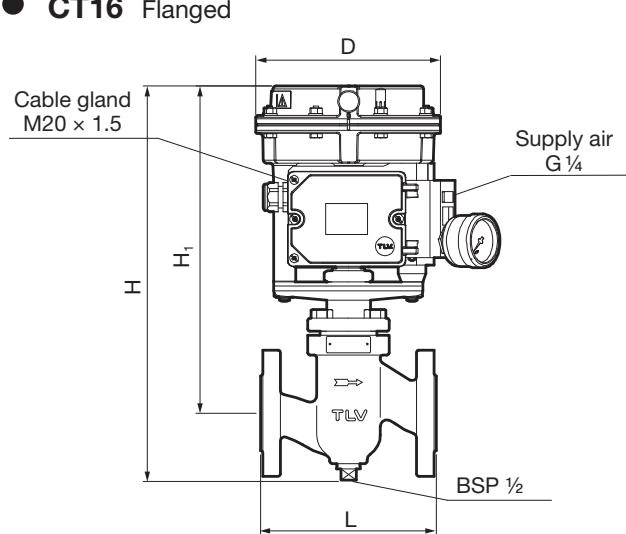
| DN | L (PN25/PN40) | Actuator Area (cm²) | H | H1 | φD | Weight (kg) |
|---|---|---|---|---|---|---|
| 15 | 130 mm | 120 | 350 mm | 292 mm | 168 mm | 8.6 |
| 20 | 150 mm | 120 | 350 mm | 292 mm | 168 mm | 9.1 |
| 25 | 160 mm | 120 | 355 mm | 292 mm | 168 mm | 10 |
| 32 | 180 mm | 120 | 380 mm | 297 mm | 168 mm | 15 |
| 40 | 200 mm | 120 | 380 mm | 297 mm | 168 mm | 16 |
| 50 | 230 mm | 120 | 385 mm | 297 mm | 168 mm | 17 |
(Weight is for DIN PN 25 in ductile cast iron)
| DN | 15 | 20 | 25 | 32 | 40 | 50 |
|---|---|---|---|---|---|---|
| Kvs (DIN) | 4.0 | 6.3 | 10 | 16 | 25 | 35 |
| Cv (UK) | 3.9 | 6.1 | 9.7 | 15.5 | 24 | 34 |
| Cv (US) | 5.0 | 7.5 | 12 | 20 | 30 | 40 |
| Seat Diameter (mm) | 12 | 24 | 24 | 32 | 38 | 48 |
Blowdown: Before installing the product, be sure to blow down all piping thoroughly. Blowdown is especially important for newly installed piping or after the system has been shut down for a long period of time.
Installation Angle: Install the product so that the arrow mark on the body points horizontally in the direction of flow, and it should be installed horizontally in the piping with the actuator at the top. Allowable inclination is 10 degrees in the fore-aft direction and 15 degrees in the plane perpendicular to the flow line.
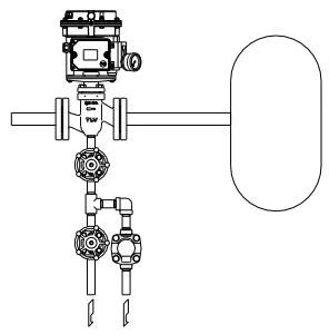
Drainage Port Usage Example: The threaded condensate drainage port at the bottom of the body makes possible installation of a blow valve or steam/air trap. Because the condensate drainage port is located on the primary side of the product, condensate flowing in the primary side piping can quickly be eliminated, contributing to prevention of valve seat erosion and rapid start-up of the equipment.
| Problem | Cause | Remedy |
|---|---|---|
| Valve Leakage | The pressure of the air supply to the actuator or positioner is too high | Adjust the pressure of the air supply for the positioner to match the pressure in the product specifications. |
| The positioner's zero point is miscalibrated | Adjust the positioner's zero point. | |
| The inlet pressure for the control valve is too high | Decrease the inlet pressure to the maximum operating pressure (PMO) or less. | |
| The valve plug and valve seat are off-center | Reassemble the valve bonnet section correctly. | |
| There is a problem with the sealing surfaces of the valve plug and valve seat | Replace with a new valve plug & stem and valve seat. |
Explore similar products in our catalog