Up to 99.8% Efficiency

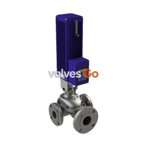
TLV CV-COS-16 electro-pneumatic control valve featuring a digital I/P positioner, built-in cyclone separator, and free float steam trap for process applications.
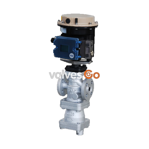
TLV CV-COS-16 electro-pneumatic control valve features a digital I/P positioner combined with a compact pneumatic actuator. It is equipped with a built-in cyclone separator and a self-modulating free float steam trap to provide dry, high-quality steam supply, improving productivity and product quality for process applications.
Safety Warning
NEVER apply direct heat to the float. The float may explode due to increased internal pressure, causing accidents leading to serious injury or damage to property and equipment.
Caution
DO NOT use the product in excess of the maximum operating pressure differential. Such use could make discharge through the steam trap impossible (blocked). Take measures to prevent people from coming into direct contact with product outlets.
| Model | CV-COS-16 |
|---|---|
| Body Material | Ductile Cast Iron / Cast Stainless Steel |
| Connection | Flanged |
| Size (DN) | 15, 20, 25, 40, 50 |
| Max. Operating Temperature (TMO) | 220 °C |
| Leak Rate Class | Class IV / Metal sealing |
| Characteristic | Equal percentage |
| Rangeability | 50 : 1 |
| Applicable Fluid | Steam |
| Fail-safe Position | Valve CLOSED (Air to Open) |
|---|---|
| Motive Medium | Oil-free air, filtered to 5 μm |
| Electrical Input Signal | 4 to 20 mA |
| Air Supply Pressure | 3.7 to 6 barg |
| Ambient Temperature Range | -25 to +80 °C |
| Protection Class | IP 66 |
| Intrinsically Safe Rating (optional) | ATEX II 2G Ex ia IIC T4 |
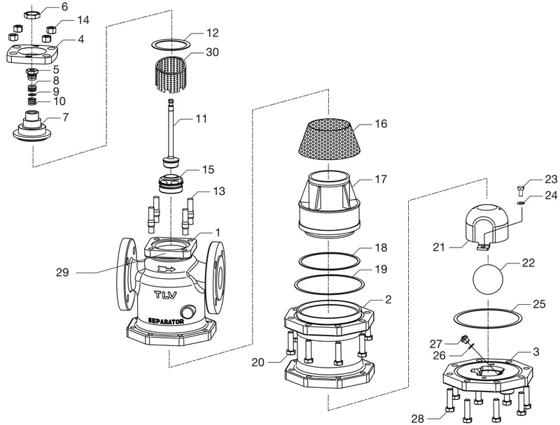
| No. | Description | No. | Description |
|---|---|---|---|
| 1 | Main Body | 16 | Separator Screen |
| 2 | Separator Body | 17 | Separator |
| 3 | Trap Cover | 18 | Wave Spring |
| 4 | Flange | 19 | Valve Seat Gasket |
| 5 | Guide Bushing | 20 | Separator Body Bolt |
| 6 | Valve Bonnet Nut | 21 | Float Cover |
| 7 | Valve Bonnet | 22 | Float |
| 8 | Stuffing Box V-ring Packing | 23 | Float Cover Bolt |
| 9 | Stuffing Box Washer | 24 | Spring Washer |
| 10 | Stuffing Box Spring | 25 | Trap Cover Gasket |
| 11 | Valve Plug & Stem | 26 | Trap Valve Seat Gasket |
| 12 | Valve Bonnet Gasket | 27 | Trap Valve Seat |
| 13 | Bolt | 28 | Trap Cover Bolt |
| 14 | Nut | 29 | Nameplate |
| 15 | Main Valve Seat | 30 | Silencer |
| Problem | Cause | Remedy |
|---|---|---|
| Valve Leakage | Pressure of air supply to actuator/positioner is too high | Adjust air supply pressure to match specifications |
| Positioner's zero point is miscalibrated | Adjust positioner's zero point | |
| Inlet pressure is too high | Decrease inlet pressure to PMO or less | |
| Valve plug and valve seat are off-center | Reassemble valve bonnet section correctly | |
| Problem with sealing surfaces of plug and seat | Replace with new valve plug & stem and valve seat |
| Problem | Cause | Remedy |
|---|---|---|
| Steam is blowing | Build-up of dirt on trap valve seat or float | Clean or replace trap valve seat or float |
| Body is installed tilted | Correct the installation | |
| Float is deformed | Replace with a new float | |
| No condensate is discharged | Primary pressure exceeds trap maximum working pressure | Decrease inlet pressure to PMO or less |
| Water is inside the float | Replace with a new float | |
| Output piping or trap valve seat is clogged | Clean or modify piping/seat |
Explore similar products in our catalog