


PN25

The TLV DR20 and A-DR20 are compact stainless steel direct-acting pressure reducing valves for steam and air systems, supporting up to 1.6 MPaG primary pressure.
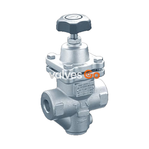
The TLV DR20 direct-acting pressure reducing valve for steam and air is capable of reducing from primary pressures of between 0.2 and 1.6 MPaG to secondary pressures between 0.014 and 1.0 MPaG. The TLV A-DR20 direct-acting pressure reducing valve for air is capable of reducing from primary pressures of between 0.2 and 1.0 MPaG to secondary pressures between 0.014 and 0.9 MPaG. Made of stainless steel for superior durability, they are designed for a long service life.
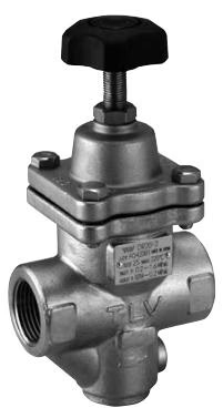
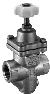
For the A-DR20, fluorine rubber is used in the seating area, inlaid in the main valve.
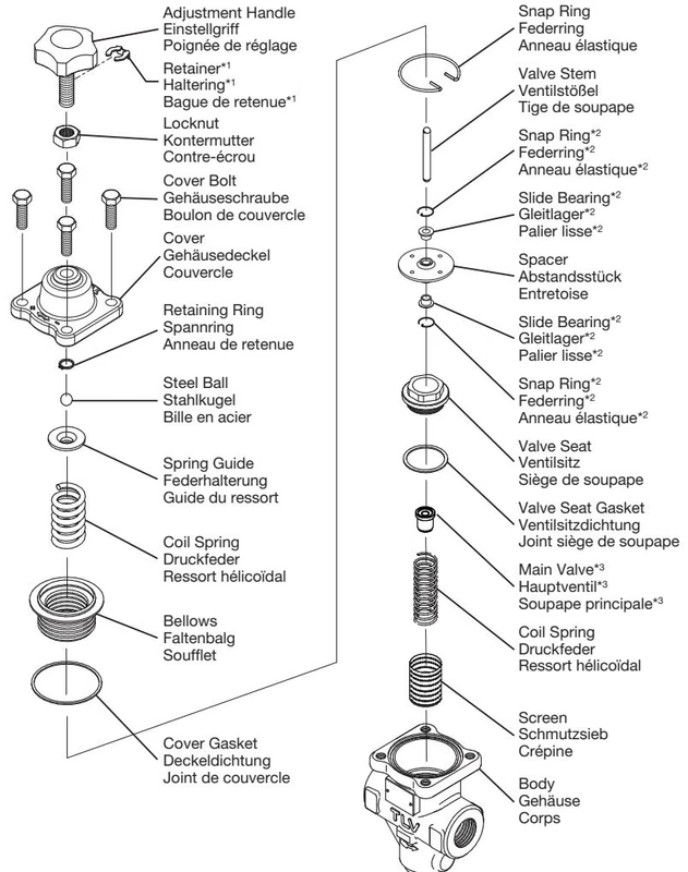
| No. | Description |
|---|---|
| 1 | Body |
| 2 | Cover |
| 3 | Screen |
| 4 | Coil Spring |
| 5 | Main Valve |
| 6 | Valve Seat Gasket |
| 7 | Valve Seat |
| Model | Applicable Fluids |
|---|---|
| DR20 | Steam, Air |
| A-DR20 | Air |
| Model | DR20-2 | DR20-6 | DR20-10 |
|---|---|---|---|
| Primary Pressure Range | 0.2 – 1.6 MPaG | 0.2 – 1.6 MPaG | 0.6 – 1.6 MPaG |
| Adjustable Pressure Range* | 0.014** – 0.2 MPaG | 0.18 – 0.6 MPaG | 0.54 – 1.0 MPaG |
| Minimum Adjustable Flow Rate | Steam: 20 kg/h, Air: 5% of rated flow rate | Steam: 20 kg/h, Air: 5% of rated flow rate | Steam: 20 kg/h, Air: 5% of rated flow rate |
| Model | A-DR20-2 | A-DR20-6 | A-DR20-10 |
|---|---|---|---|
| Primary Pressure Range | 0.2 – 1.0 MPaG | 0.2 – 1.0 MPaG | 0.6 – 1.0 MPaG |
| Adjustable Pressure Range* | 0.014** – 0.2 MPaG | 0.18 – 0.6 MPaG | 0.54 – 0.9 MPaG |
| Minimum Adjustable Flow Rate | Air: 5% of rated flow rate | Air: 5% of rated flow rate | Air: 5% of rated flow rate |
* Secondary pressure must not exceed 90% of primary pressure.** But not less than 1/30 of primary pressure.
WARNING
To avoid malfunctions, product damage, accidents or serious injury, install properly and DO NOT use this product outside the specification range. Local regulations may restrict the use of this product to below the conditions quoted.
INFO
Installation, inspection, maintenance, repairs, disassembly, adjustment and valve opening/closing should be carried out only by trained maintenance personnel. Install for use under conditions in which no freeze-up or water hammer will occur.
To ensure stable flow and prevent chattering, install the pressure reducing valve on straight runs of piping:
Install any required on-off valve on the inlet side of the DR20/A-DR20 as near to the boiler or air compressor as possible. Installing it at the outlet will cause heavy chattering and potential damage. A slow-acting motorized on-off valve is recommended for steam systems to prevent water hammer.
A control valve should be installed close to the equipment (downstream of the DR20/A-DR20). A safety valve should be installed downstream of the control valve, on or directly before the equipment inlet.
Make sure the DR20/A-DR20 is installed on horizontal piping with the adjustment handle facing up. The allowable inclination is 10° front-to-back and 15° horizontally.
If the secondary side flow velocity exceeds 30 m/s (100 ft/s), install a diffuser.
Employ 2-stage pressure reduction if the required reduction is not possible due to operating range limitations.
Perform inspection and maintenance at least once a year. Wait for the body to cool before removing the valve from the line.
| Parts | Inspection Procedure |
|---|---|
| Body, Cover | Check inside for damage, dirt, grease, oil film, rust or scale |
| Screen | Check for clogging, damage or deformation |
| Valve and Valve Seat | Check for rust, scale, oil film, wear or damage |
| Valve Stem | Check for wear or damage |
| Bellows | Check for cracks, damage or deformation |
| Gaskets | Check for warping or damage |
| Problem | Cause | Remedy |
|---|---|---|
| Secondary pressure does not increase | No steam/air supplied, valves closed, or screen clogged | Check piping, valves, and clean screens |
| Flow rate exceeds specifications or adjustable range | Check model selection | |
| Adjustment is difficult and set pressure varies | Flow rate too low or high fluctuation | Check flow rate, check model selection |
| Buildup on the valve stem | Clean and inspect valve stem and spacer | |
| Secondary pressure abruptly rises as high as primary pressure | Adjustment handle seized, spacer holes clogged, or parts damaged | Clean parts, replace handle, spacer, or bellows |
Explore similar products in our catalog




