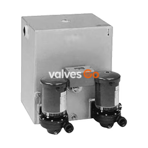
3450 RPM Motors

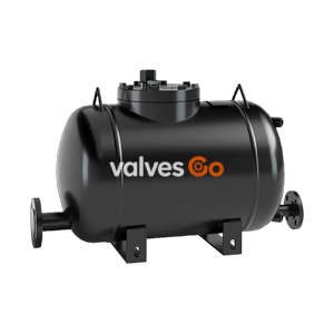
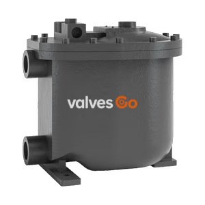
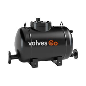
TLV GP10L PowerTrap mechanical pump for discharging condensate from vacuum-pressure or low-pressure areas. Suitable for open systems with up to 1.05 MPaG motive medium pressure.
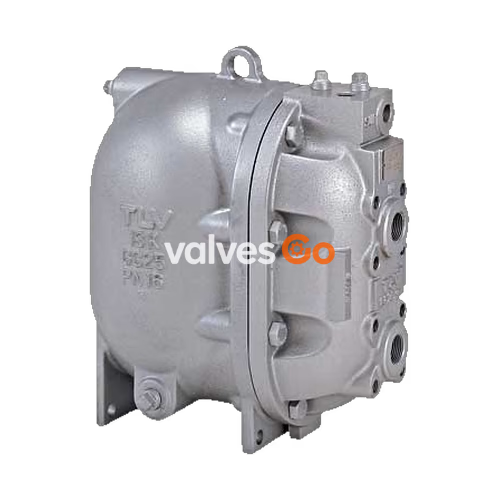
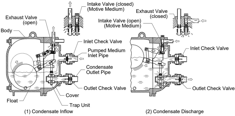
The TLV GP10L PowerTrap is a mechanical pump designed to discharge liquid from vacuum-pressure or low-pressure areas to high-pressure areas, or from lower to higher elevations. It is primarily used for condensate recovery on open systems. The related GT10L model features an additional built-in steam trap function, making it suitable for closed systems where the inlet pressure may alternately be lower or higher than the outlet pressure.
WARNING
Install properly and DO NOT use this product outside the recommended operating pressure, temperature, and other specification ranges. Use only under conditions in which no freeze-up or water hammer will occur. Freezing or water hammer may damage the product, leading to fluid discharge, which may cause burns or other injury.
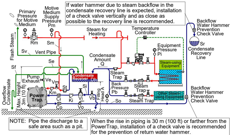
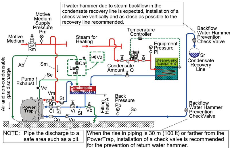
There are two main types of delivery systems (piping methods): the closed system and the open system. The selection of the GP model or GT model is determined by the system type.
| Type of System | Closed System | Open System |
|---|---|---|
| System Overview | Condensate Recovery Line directly connected | Discharge to Atmosphere via Vent Pipe and Receiver |
| Benefits | No flash steam discharge. Use with vacuum equipment possible (providing sufficient differential pressure). | Collection of condensate from multiple equipment. Can be used where trap is lower than receiver. |
| Notes | Only one piece of equipment possible per system. Minimum height requirement ensures condensate flows naturally by gravity (approx. 0.3 m or 0.5 m). | Separate steam trap required for each piece of equipment. Requires venting pipe to discharge flash steam to atmosphere. |
| Model | Mechanical pump with built-in trap (GT10L) | Mechanical pump (GP10L) |


| Model | Max. Operating Pressure (PMO) | Motive Medium Pressure Range | Max. Allowable Back Pressure |
|---|---|---|---|
| GP10L, GT10L | 1.05 MPaG (150 psig) | 0.03 - 1.05 MPaG (5 - 150 psig) | 0.05 MPa less than motive medium pressure used |
| GP14L, GT14L, GP14M, GT14M | 1.4 MPaG (200 psig) | 0.03 - 1.4 MPaG (5 - 200 psig) | 0.05 MPa less than motive medium pressure used |
The GP10L and GT10L models utilize screwed connections (Rc(PT), NPT, or BSP) for the condensate inlet and outlet.
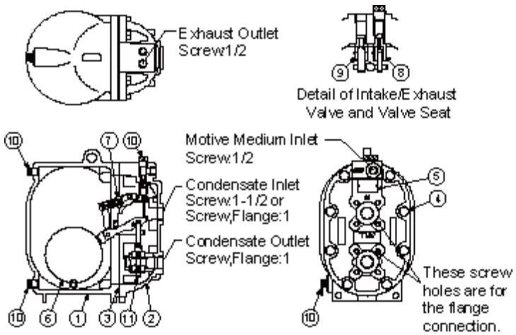
| No. | Part Name | No. | Part Name |
|---|---|---|---|
| 1 | Body | 7 | Snap-action Unit |
| 2 | Cover | 8 | Intake Valve Unit |
| 3 | Cover Gasket | 9 | Exhaust Valve Unit |
| 4 | Cover Bolt | 10 | Plug |
| 5 | Nameplate | 11 | Trap Unit (GT10L only) |
| 6 | Float |
Fluids that can be discharged through the PowerTrap are limited to steam condensate and water. A 40-mesh or finer strainer should be installed on both the pumped medium inlet pipe and the motive medium supply pipe.
INFO
A condensate receiver is necessary for storing condensate during pumping in open systems. If the exhaust line must discharge to the atmosphere, a sound level of approximately 90 dB may be emitted for two to three seconds. A silencer may be installed if soundproofing is necessary.
Explore similar products in our catalog