PN16
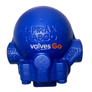
The Spirax Sarco APT10 and APT10SS automatic pump traps are screwed displacement receivers, capable of automatically trapping or pumping depending on line conditions. They are operated by steam to remove condensate from process and heating plant under all operating conditions.
The Spirax Sarco APT10 and APT10SS automatic pump traps are screwed displacement receivers, pressure rated to PN10 and PN16 respectively. Both units are capable of automatically trapping or pumping, depending on line conditions. The units are operated by steam and are used to remove condensate from process and heating plant under all operating conditions, including vacuum. The shell body and cover are available in SG iron (designated APT10) and stainless steel (designated APT10SS).
The APT10 is available with a standard blue paint finish or coated in ENP (Electroless Nickel Plate), while the APT10SS is available with electropolish as the standard finish.
This product is available with certification to EN 10204 3.1. Note: All certification/inspection requirements must be stated at the time of order placement.
This product fully complies with the requirements of the European Pressure Equipment Directive 2014/68/EU, ATEX Directive 2014/34/EU and carries the CE and Ex marks when so required.
Shell designed in accordance with A.D. Merkblatter/ASME VIII.
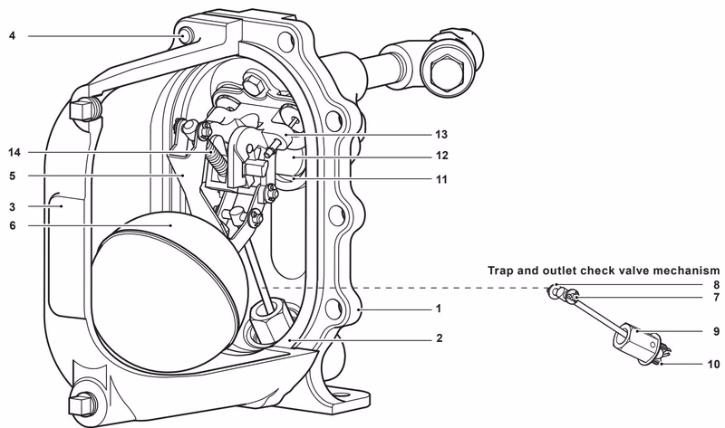
| No. | Part | Material | |
|---|---|---|---|
| 1 | Cover | APT10 | SG iron EN-GJS-40018-LT (5.3103)/ASTM A395 |
| APT10SS | Stainless steel GX5CrNi19-10 (1.4308)/A351 CF8 | ||
| 2 | Cover gasket | Graphite laminate with stainless steel insert | |
| 3 | Body | APT10 SG iron | EN-GJS-40018-LT (5.3103)/ASTM A395 |
| APT10SS Stainless steel | GX5CrNi19-10 (1.4308)/A351 CF8 | ||
| 4 | Cover bolts | Stainless steel | BS EN ISO 3506 Gr.A2-70 |
| 5 | Pump trap lever | Stainless steel | BS 1449 304 S15 |
| 6 | Float | Stainless steel | BS 1449 304 S16 |
| 7 | Pivot shaft | Stainless steel | BS 970 431 S29/ASTM A276 431 |
| 8 | Washer | Stainless steel | BS 1449 316 |
| 9 | Trap housing | Stainless steel | BS 970 431 S29/ASTM A276 431 |
| 10 | Ball | Stainless steel | ASTM A276 440 B |
| 11 | Seat (inlet check valve) | Stainless steel | AISI 420 |
| 12 | Flap (inlet check valve) | Stainless steel | BS 3146 ANC 4B |
| 13 | Pump mechanism bracket | Stainless steel | BS 3146 ANC 4B |
| 14 | Spring (pump) | Stainless steel | BS 2056 302 S26 Gr.2 |
| 15 | Split pin | Stainless steel | BS 1574 |
| 16 | Exhaust seat | Stainless steel | BS 970 431 S29/ASTM A276 431 |
| 17 | Inlet valve and seat assembly | Stainless steel | BS 970 431 S29 |
| 18 | Exhaust valve | Stainless steel | BS 3146 ANC 2 |
| 19 | Valve seat gasket | Stainless steel | BS 1449 409 S19 |
| 20 | Pump mechanism bolt | Stainless steel | BS EN ISO 3506 Gr.A2-70 |
| 21 | Float bolt | Stainless steel | BS EN ISO 3506 Gr.A2-70 |
| 22 | Trap 1st stage valve | Stainless steel | BS 970 431 S29/ASTM A276 431 |
| 23 | Trap gasket | Stainless steel | BS 1449 409 S19 |
| 24 | Actuator arm | Stainless steel | BS 3146 ANC 2 |
| 25 | Name-plate | Stainless steel | BS 1449 304 S16 |
| 26 | Drain plug | APT10 | Carbon steel C22.8/A105 |
| APT10SS | Stainless steel 1.4308/A351 CF8 | ||
| 27 | Motive supply strainer | APT10 | SG iron EN-GJS-400-15 |
| APT10SS | Stainless steel 1.4409/A351 CF3M | ||
| 28 | Threaded barrel | APT10 | Steel pipe |
| APT10SS | Stainless steel |
Size: DN20 x DN20
| Inlet | Fluid connections Outlet | Motive/Exhaust |
|---|---|---|
| DN20 (3/4") | DN20 (3/4") | DN15 (1/2") |
| BSP T Rp (ISO 7-1) | BSP T Rp (ISO 7-1) | BSP |
| NPT | NPT | NPT |
| APT10 | APT10SS | |
|---|---|---|
| Body design conditions | PN10 | PN16 |
| Maximum motive inlet pressure | 4.5 bar g (65 psi g) | 4.5 bar g (65 psi g) |
| Maximum operating pressure | 4.5 bar g (65 psi g) | 4.5 bar g (65 psi g) |
| Maximum backpressure | 4.0 bar g (58 psi g) | 4.0 bar g (58 psi g) |
| Maximum operating temperature | 155°C (311°F) | 155°C (311°F) |
| Minimum operating temperature | -10°C (14°F) | -10°C (14°F) |
| Temperature limits (Ambient) | -10°C to 200°C (14°F to 392°F) | -10°C to 200°C (14°F to 392°F) |
| Designed for a maximum cold hydraulic test pressure of: | 15.0 bar g (217 psi g) | 24.0 bar g (348 psi g) |
For full details see the Installation and Maintenance Instructions supplied with the product.
For full capacity details for a specific application consult Spirax Sarco. To accurately size the pump trap, the following data is required.
| Size | DN20 x DN20 |
|---|---|
| Pump discharge/cycle | 2.6 litres (0.55 gallons) |
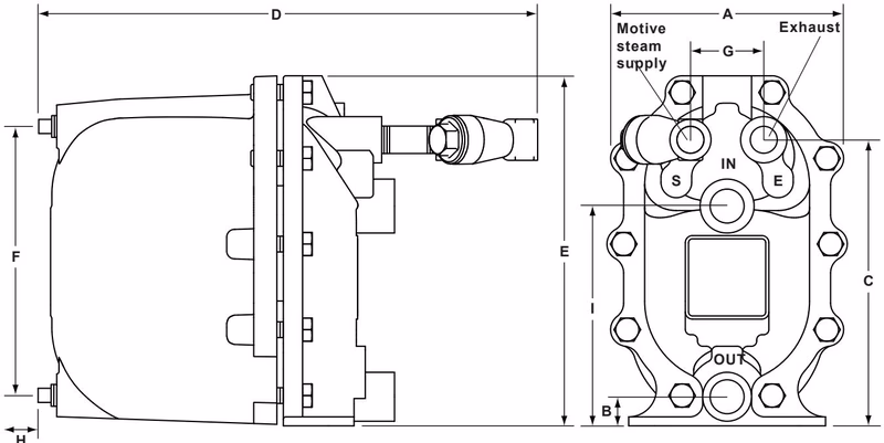
| Size | A | B | C | D | E | F | G | H | I | Weight |
|---|---|---|---|---|---|---|---|---|---|---|
| DN20 × DN20 | 187 (7.4) | 23 (0.9) | 223 (8.8) | 398 (15.6) | 273 (10.7) | 209 (8.2) | 57 (2.2) | 135 (5.3) | 171 (6.7) | 14 (31) |
The pump trap shall be a Spirax Sarco automatic pump trap type APT10 operated by steam to 4.5 bar g (65 psi g.). No electrical energy shall be required. Body construction from SG iron (5.3103 or ASTM A395) with a swing type inlet check valve and ball type outlet check valve. The internal trap mechanism shall contain a stainless steel float connected to an internal trap. The pump, trap and check valve mechanisms shall be incorporated into the same body envelope with no external seals or glands and shall be capable of operating with a minimum of 200 mm (7.8") installation head from the base of the unit.
Example: 1 off Automatic pump trap, type APT10, DN20 x DN20 (3/4" x 3/4"), complete with motive supply strainer screwed BSP with BSP T Rp (ISO 7-1) motive fluid connections.
The spare parts available are shown in solid outline. Parts drawn in a grey line are not supplied as spares.
| Part | Description | Item No. |
|---|---|---|
| A | Cover gasket | 2 |
| B | Inlet check valve | 2, 12 |
| C | Spring and actuator arm | 2, 14, 24 |
| D | Float | 2, 5, 6, 21 |
| E | Trap and outlet check valve mechanism | 2, 7, 8, 9, 10, 22, 23 |
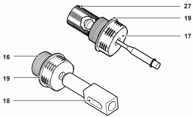
| F | Inlet/exhaust valve and seat kit | 2, 16, 17, 18, 19 |
| G | Motive supply strainer (Fig. 12 SG iron or Fig 16L Stainless Steel) - see separate literature | 27 |
Please note: For customer convenience, spares are supplied in kits to ensure all the appropriate replacement parts are available e.g. when an inlet /exhaust valve and seat assembly is ordered, all replacement split pins, washers and gaskets will be provided in addition to the key components listed.
Always order spares by using the description given in the column headed 'Available spares' and state the size and type of unit. Example: 1 off Inlet /exhaust valve and seat kit for a Spirax Sarco DN20 x DN20 (3/4" x 3/4") APT10 automatic pump trap.
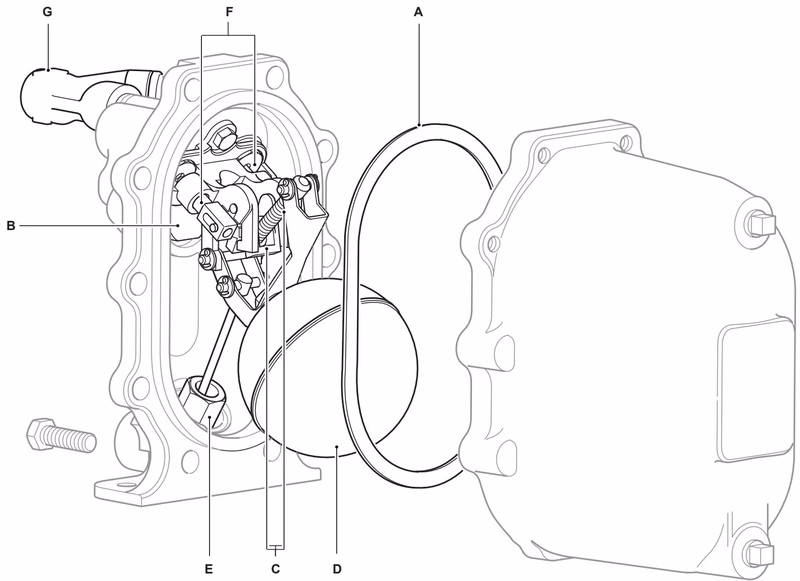
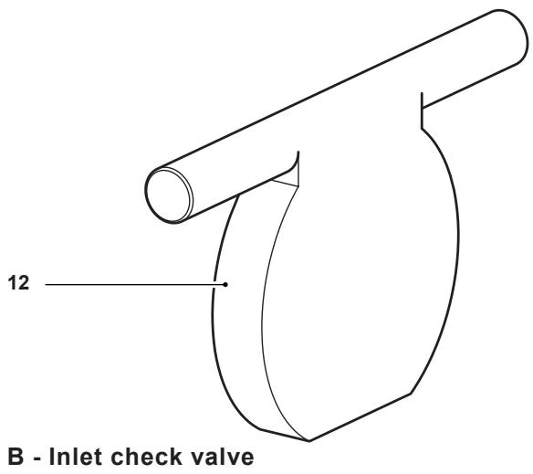
B - Inlet check valve
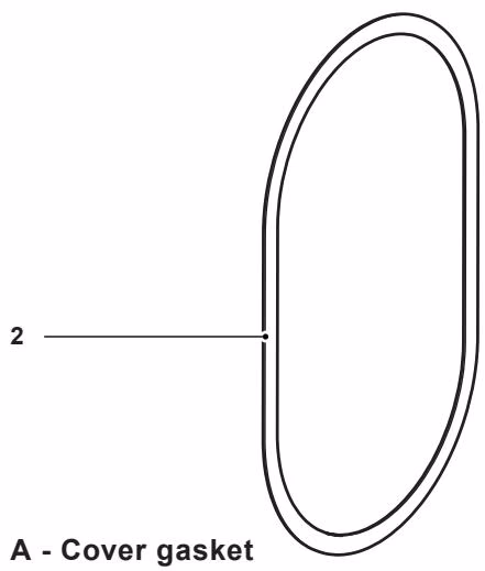
A - Cover gasket

C - Spring and actuator arm
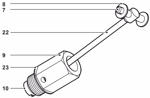
E - Trap and outlet check valve mechanism
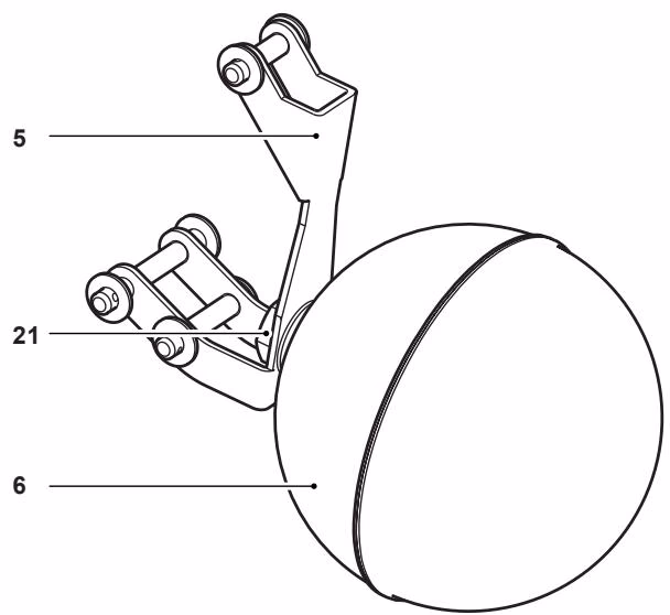
D - Float
F - Inlet / exhaust valve and seat kit