3450 RPM Motors

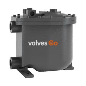
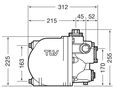
TLV GT5C PowerTrap compact mechanical pump with built-in steam trap. Features extremely low 155 mm filling head, handles high-temperature condensate.
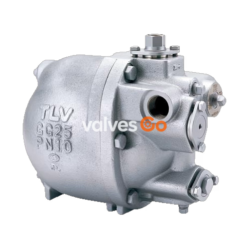
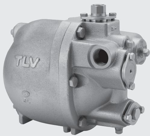
The TLV GT5C PowerTrap is a compact mechanical pump with a built-in steam trap, featuring a linear inlet/outlet, low filling head, and simple piping installation. It is highly effective for small heat exchangers and steam/air heaters that often operate under stall conditions. The unit functions as a standard steam trap when equipment pressure is higher than back pressure, and automatically switches to a pumping function when equipment pressure drops, using motive steam to eliminate accumulated condensate. This prevents stall and eliminates water hammer upon restart.
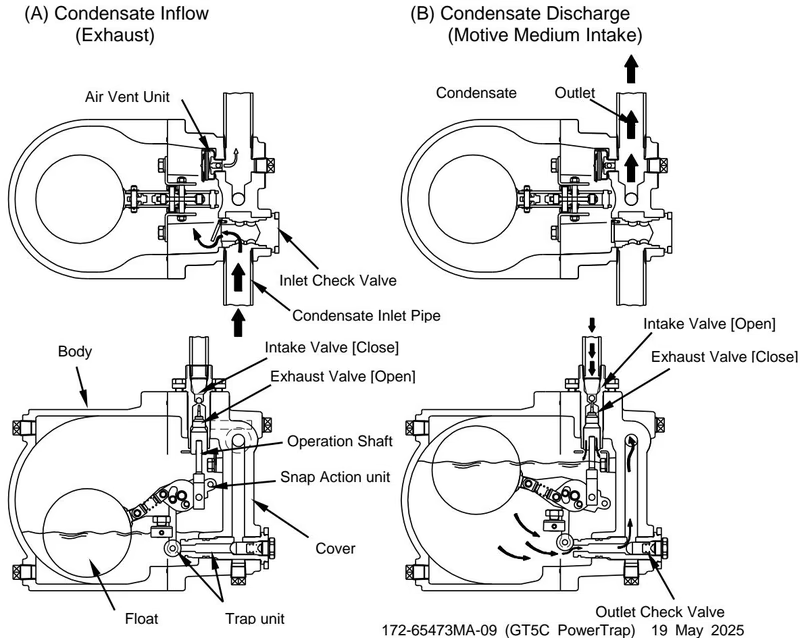
When condensate flows from the inlet pipe through the inlet check valve into the body, the float rises. When the equipment pressure is greater than the back pressure, the condensate passes through the outlet check valve and is discharged normally.
If the equipment pressure is less than or equal to the back pressure, condensate is not discharged and collects in the body. As the float rises to its high level, the snap-action unit quickly closes the exhaust valve and opens the intake motive medium valve. The motive medium pressure causes the internal pressure to exceed the back pressure, forcing the condensate out. As condensate is discharged, the float descends, ultimately closing the intake valve and opening the exhaust valve to revert to the inflow status.
The inlet piping is connected to the inlet in the same way as a standard steam trap. The condensate inlet pipe acts as a condensate reservoir. The minimum filling head is 155 mm. 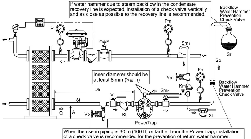
The pumping discharge capacity can be increased by raising the filling head (e.g., 300 mm). An exhaust pipe must be connected from the exhaust outlet to the top of the condensate inlet pipe. 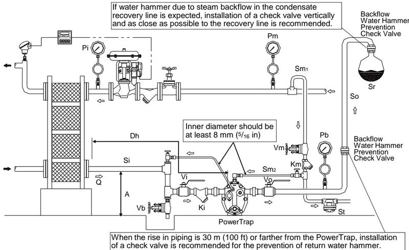
The reservoir must have capacity sufficient to store the condensate produced during PowerTrap operation and discharge. If the motive medium supply pressure divided by back pressure equals 2 or greater, the length of the condensate reservoir pipe can be reduced by 50%.
| Condensate Amount (kg/h) | 25 mm (1") | 32 mm (1 1/4") | 40 mm (1 1/2") | 50 mm (2") | 80 mm (3") |
|---|---|---|---|---|---|
| 50 | 0.6 m | - | - | - | - |
| 100 | 1.2 m | 0.6 m | 0.4 m | - | - |
| 150 | 1.8 m | 1.0 m | 0.6 m | 0.4 m | - |
| 200 | 2.4 m | 1.3 m | 0.8 m | 0.5 m | - |
| 300 | - | 2.0 m | 1.2 m | 0.7 m | - |
| 400 | - | 2.6 m | 1.5 m | 1.0 m | - |
| 500 | - | - | 2.0 m | 1.2 m | 0.5 m |
Tolerance Angle for Installation
The product should be inclined no more than 3°. Make sure the body is installed with the raised TLV lettering on the body horizontal.
Explore similar products in our catalog