


PN16

TLV J7.2X cast iron free float steam trap for medium-size process equipment. Features thermostatic air venting (X-element), flanged connection, and up to 13 barg max operating pressure.
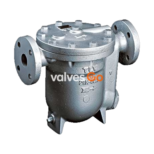
TLV J7.2X is a reliable and durable cast iron steam trap with tight shut-off designed for medium-size process equipment. It features a self-modulating free float that provides continuous, smooth, low velocity condensate discharge as process loads vary, alongside a built-in thermostatic capsule (X-element) that automatically vents air until close to steam temperature.
| Model | J7.2X |
|---|---|
| Connection | Flanged |
| Size | DN 40, 50 |
| Orifice No. | 0.5, 1, 2, 5, 10, 13 |
| Maximum Operating Pressure (PMO) | 0.5, 1, 2, 5, 10, 13 barg |
| Maximum Operating Temperature (TMO) | 200 °C |
| Subcooling of X-element Fill | up to 6 °C |
| Type of X-element | C6 |
Design Conditions
Maximum Allowable Pressure (PMA): 13 barg. Maximum Allowable Temperature (TMA): 200 °C. These are pressure shell design conditions, not operating conditions.
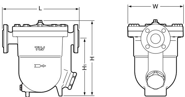
| DN | L (DIN 2501) | H | H1 | φW | Weight (kg) |
|---|---|---|---|---|---|
| 40 | 366 mm | 330 mm | 244 mm | 243 mm | 33 |
| 50 | 370 mm | 340 mm | 249 mm | 243 mm | 35 |
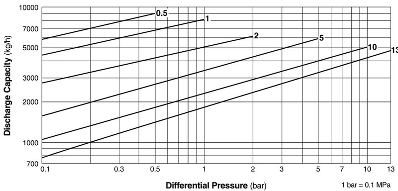
Sizing Recommendation
Line numbers within the graph above refer to orifice numbers. Differential pressure is the difference between the inlet and outlet pressure of the trap. Capacities are based on continuous discharge of condensate 6 °C below saturated steam temperature. Recommended safety factor: at least 1.5.
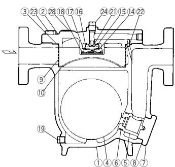
| No. | Description | No. | Description |
|---|---|---|---|
| 1 | Body | 15 | X-element Guide |
| 2 | Cover | 16 | Spring Clip |
| 3 | Cover Gasket | 17 | X-element Cover |
| 4 | Float | 18 | Snap-Ring |
| 5 | Orifice | 19 | Drain Plug |
| 6 | Orifice O-Ring | 20 | Drain Plug Gasket |
| 7 | Orifice Holder Plug | 21 | Air Vent Valve Seat |
| 8 | Orifice Plug Gasket | 22 | Connector |
| 9 | Screen | 23 | Cover Bolt |
| 10 | Screen Holder | 24 | Plug |
| 11 | Screen Holder Retainer | 25 | Plug Gasket |
| 12 | Float Cover | 28 | Nameplate |
| 13 | Snap-Ring | ||
| 14 | X-element |
DANGER
NEVER apply direct heat to the float. The float may explode due to increased internal pressure, causing accidents leading to serious injury or damage to property and equipment.
WARNING
Install properly and DO NOT use this product outside the recommended operating pressure, temperature and other specification ranges. DO NOT use this product in excess of the maximum operating pressure differential. Such use could make discharge impossible.
Allowable Inclination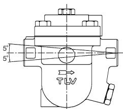
Piping Best Practices
Operational inspections should be performed at least twice per year. Before attempting to open the trap, close the inlet and outlet isolation valves and wait until the trap has cooled completely.
| Parts Inspection | Procedure |
|---|---|
| Body, Cover | Check inside for damage, dirt, grease, oil film, rust or scale |
| Gaskets | Check for warping or damage |
| X-element | Check for damage |
| Screen | Check for clogging, corrosion or damage |
| Float | Check for deformation, damage, oil film or water inside |
| Valve Seat, Orifice | Check for rust, scale, oil film, wear or damage |
Visually inspect the trap when it discharges to the atmosphere to help determine immediate maintenance needs.
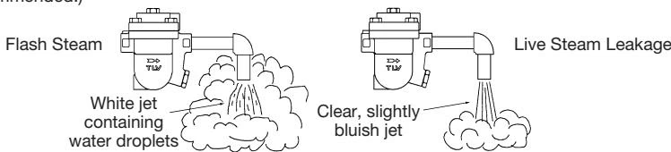
| Problem | Cause | Remedy |
|---|---|---|
| No condensate is discharged (blocked) | Float is damaged or filled with condensate | Replace the float |
| Orifice, screen or piping is clogged with rust/scale | Clean | |
| Steam-locking has occurred | Blowdown through bypass or close inlet valve and allow trap to cool | |
| Steam is discharged or leaks from trap outlet | Rust and scale have accumulated around the orifice or under the float | Clean |
| Orifice is damaged | Replace the orifice | |
| Float is deformed or coated with scale | Clean or replace the float | |
| Trap is installed above the maximum allowable inclination angle | Correct the installation |




