Cast Iron

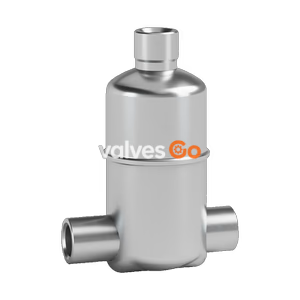
TLV JA3D Free Float Air Trap in zinc alloy. Discharges oil and condensate continuously. Up to 1.6 MPaG, 100°C. For horizontal or vertical installations.
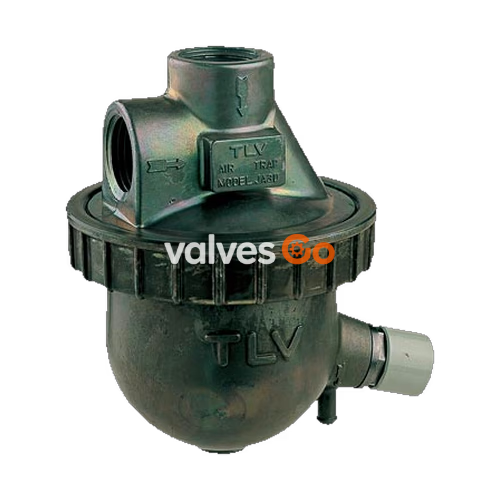
The TLV JA3D is a free float air trap constructed of zinc alloy. It is suitable for air systems with pressures up to 1.6 MPaG (230 psig) and temperatures up to 100 °C (212 °F). The trap discharges oil and condensate continuously and automatically without adjustment.
This trap has two inlet ports – one at the top and one at the side of the trap. Only one port can be used as an inlet. The other port should be used to connect a pressure-balancing line to prevent air binding.
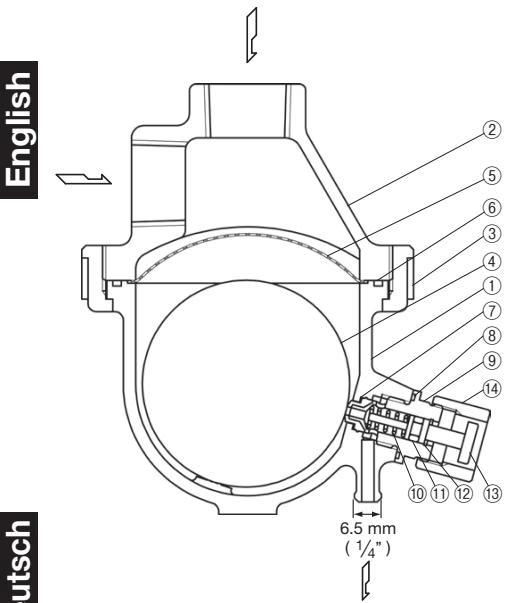
| No. | Description | No. | Description |
|---|---|---|---|
| 1 | Body | 8 | Valve Seat Holder Gasket |
| 2 | Cover | 9 | Valve Seat Holder |
| 3 | Union Nut | 10 | Coil Spring |
| 4 | Float | 11 | Plunger O-Ring |
| 5 | Screen | 12 | Snap Ring |
| 6 | Cover Gasket | 13 | Plunger |
| 7 | Valve Seat | 14 | Guard Bushing |
| Model & Connection (S = Screwed) | Size mm (in) | Maximum Operating Temperature TMO °C (°F) | (1) Maximum Operating Pressure PMO MPaG (psig) (2) Maximum Differential Pressure ∆PMX MPa (psi) |
|---|---|---|---|
| JA3D S | 15 (1/2) | 100 (212) | (1) & (2) 1.6 (230) |
1 MPa = 10.197 kg/cm², 1 bar = 0.1 MPa
PRESSURE SHELL DESIGN CONDITIONS (NOT OPERATING CONDITIONS):
WARNING
To avoid malfunctions, product damage, accidents or serious injury, install properly and DO NOT use this product outside the specification range. Local regulations may restrict the use of this product to below the conditions quoted.
Horizontal Inclination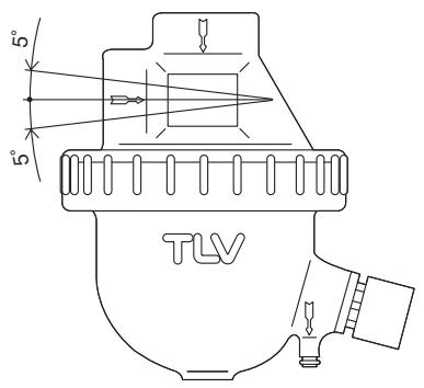
Vertical Inclination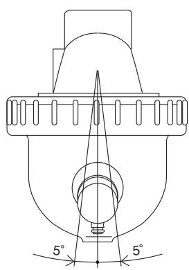
Check to make sure that the pipes connected to the trap have been installed properly.
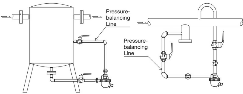
A visual inspection of the following items should be done on a daily basis to determine whether the trap is operating properly or has failed. Periodically (at least biannually) the operation should also be checked by using diagnostic equipment such as a stethoscope or thermometer.
| State | Description |
|---|---|
| Normal: | Condensate is discharged continuously and the sound of flow can be heard. If there is very little condensate, there is almost no sound of flow. |
| Blocked: | No condensate is discharged. |
| Blowing: | Air continually flows from the outlet and there is a continuous high-pitched sound of flow. |
| Air Leakage: | Air is discharged through the trap outlet together with the condensate, accompanied by a high-pitched sound. |
If the trap shows signs of blockage, blowing or air leakage, perform manual blowdown by pushing the plunger in several times with a fingertip to allow dirt and oil to be discharged through the orifice. If this does not remedy the problem, perform troubleshooting.
Operational inspections should be performed at least twice per year, or as called for by trap operating conditions. Faulty air traps may result in losses due to air leakage.
DANGER
NEVER apply direct heat to the float. The float may explode due to increased internal pressure, causing accidents leading to serious injury or property and equipment damage.
Parts Inspection Procedure
| Part | Description |
|---|---|
| Body, Cover | Check inside for dirt, grease, oil film, rust or scale |
| Gaskets | Check for warping or damage |
| Screen | Check for clogging, corrosion or damage |
| Float | Check for deformation, damage, oil film or water inside |
| Plunger O-Ring | Check for warping or damage |
| Valve Seat Opening | Check for rust, scale, oil film, wear or damage |
If the expected performance is unachievable after installation of the air trap, check the following table for the appropriate corrective measures to be taken.
| Problem | Cause | Remedy |
|---|---|---|
| No condensate is discharged (blocked) or discharge is poor | Float is damaged or filled with condensate | Replace the float |
| Orifice, screen or piping is clogged with rust, scale or dirt | Clean | |
| The trap operating pressure exceeds the maximum specified pressure, or there is insufficient differential pressure between the trap inlet and outlet | Compare specifications and actual operating conditions | |
| Air binding occurs | Check and correct pressure-balancing line and inlet piping arrangement | |
| Air is discharged or leaks from the trap outlet (blowing) (air leakage) | Orifice is clogged or rust and scale have accumulated under the float | Clean |
| Orifice is damaged | Replace the orifice | |
| Float is deformed or coated with scale | Clean or replace the float | |
| Trap is installed above the maximum allowable inclination angle | Correct the installation | |
| Vibration of trap occurs | Lengthen inlet piping, then fasten it securely | |
| Air leaks from a place other than the trap outlet | Deterioration of or damage to gaskets | Replace the gaskets |
| Improper tightening torque for cover was used | Tighten to the proper torque |
Explore similar products in our catalog