


PN16

TLV JH3LH-X stainless steel free float steam trap with X-element thermostatic air venting. Features three-point seating, DN 25 flanged connection, and max operating temperature of 240°C.
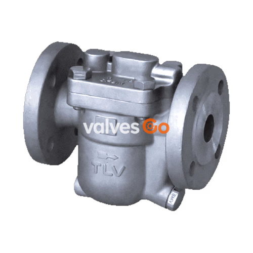
The TLV JH3LH-X is a reliable and durable stainless steel free float steam trap designed for use on small-size process equipment. It features a self-modulating free float that provides continuous, smooth, low-velocity condensate discharge as process loads vary. A constant water seal and unique three-point seating ensure a perfect steam-tight seal, even under no-load conditions. The thermostatic capsule (X-element) with a "fail open" feature vents air automatically at close-to-steam temperature, reducing start-up times and preventing air binding during operation.
Built with an integrated screen featuring a large surface area, the JH3LH-X ensures trouble-free operation. Its design allows for easy, inline access to internal parts, simplifying cleaning and reducing maintenance costs.
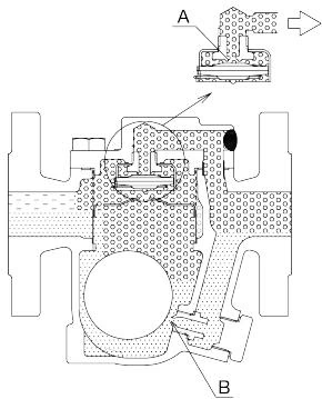
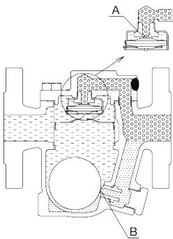
1. Initial Air and Cold Condensate Discharge At startup, before steam is supplied, the trap is cold so the X-element is contracted and the air vent valve seat (A) is open. This allows for the rapid discharge of air through the air vent valve (A) and cold condensate through the orifice (B), when steam is first supplied to the system.
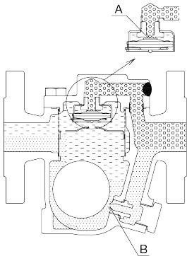
2. Condensate Discharge After the discharge of initial air and cold condensate, the heat of the inflowing steam and condensate causes the X-element to expand, closing the air vent valve (A). The rising condensate level causes the float to rise due to buoyancy, opening the orifice (B) and allowing condensate to be discharged.
3. Hot Air Discharge Should hot air flow into the trap with the steam during normal operation, the temperature of the X-element drops, causing it to momentarily contract and open the air vent valve (A), which allows for the rapid discharge of the air. After the air is discharged and steam contacts the X-element, the temperature will increase causing the air vent valve (A) to close.
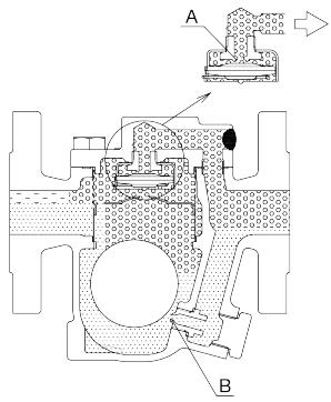
4. Closed Position When the condensate flow rate decreases, the float falls as condensate is discharged, closing off the orifice (B). A water seal is maintained at all times over the orifice (B) to prevent steam loss.
| Model | JH3LH-X |
|---|---|
| Connection | Flanged |
| Size | DN 25 |
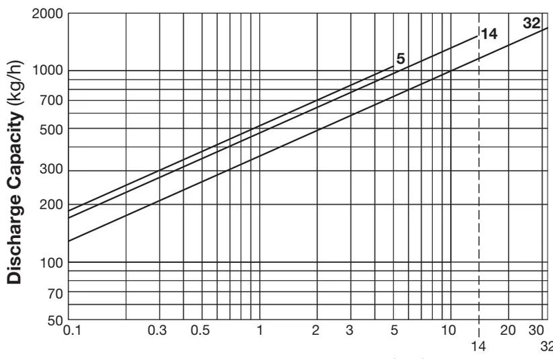
| Orifice No. | 5, 14, 32 |
| Maximum Operating Pressure (barg) PMO | 5, 14, 32 |
| Maximum Differential Pressure (bar) ΔPMX | 5, 14, 32 |
| Maximum Operating Temperature (°C) TMO | 240 |
| Subcooling of X-element Fill (°C) | up to 6 |
| Type of Air Vent | C6 |
WARNING
PRESSURE SHELL DESIGN CONDITIONS (NOT OPERATING CONDITIONS): Maximum Allowable Pressure (barg) PMA: 32. Maximum Allowable Temperature (°C) TMA: 240. To avoid abnormal operation, accidents or serious injury, DO NOT use this product outside of the specification range.
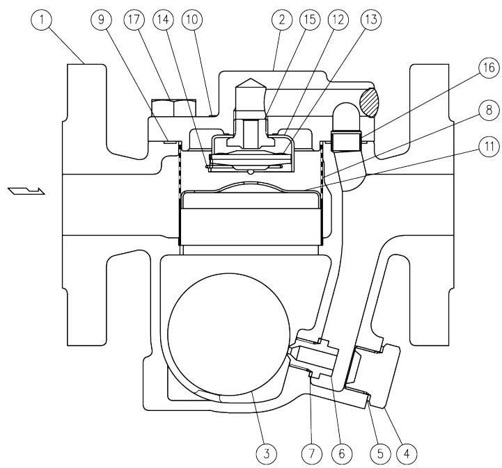
| No. | Description | Material | DIN/EN | ASTM/AISI |
|---|---|---|---|---|
| 1 | Body | Cast Stainless Steel A351/A351M Gr.CF8M | 1.4410 | - |
| 2 | Cover | Cast Stainless Steel A351/A351M Gr.CF8M | 1.4410 | - |
| 3 | Float | Stainless Steel SUS316L | 1.4404 | - |
| 4 | Orifice Plug | Cast Stainless Steel A351/A351M Gr.CF8M | 1.4410 | - |
| 5 | Orifice Plug Gasket | Stainless Steel SUS316L | 1.4404 | AISI316L |
| 6 | Orifice | - | - | - |
| 7 | Orifice Gasket | Stainless Steel SUS316L | 1.4404 | AISI316L |
| 8 | Screen inside/outside | Stainless Steel SUS430/304 | 1.4016/1.4301 | AISI430/304 |
| 9 | Cover Gasket | Graphite/Stainless Steel SUS316L | -/1.4404 | -/AISI316L |
| 10 | Nameplate | Stainless Steel SUS304 | 1.4301 | AISI304 |
| 11 | Float Cover | Stainless Steel SUS304 | 1.4301 | AISI304 |
| 12 | X-element Guide | Stainless Steel SUS304 | 1.4301 | AISI304 |
| 13 | X-element | - | - | - |
| 14 | Spring Clip | Stainless Steel SUS304 | 1.4301 | AISI304 |
| 15 | Air Vent Valve Seat | Stainless Steel SUS420F | 1.4028 | AISI420F |
| 16 | Connector | Stainless Steel SUS416 | 1.4005 | AISI416 |
| 17 | Cover Bolt | Stainless Steel A193/A193M Gr.B8M Cl.2 | 1.4401 | - |
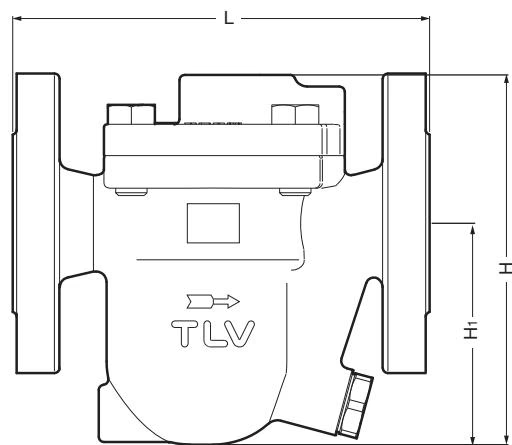
| DN | L (DIN EN 1092-2 PN40) | H | H1 | Weight (kg) |
|---|---|---|---|---|
| 25 | 160 | 140 | 85 | 5.1 |
DANGER
DO NOT use traps under conditions that exceed maximum differential pressure, as condensate backup will occur!
WARNING
NEVER apply direct heat to the float. The float may explode due to increased internal pressure, causing accidents leading to serious injury or damage to property and equipment.
Table of Tightening Torques
| Part Name & No. | Torque (N·m) | Distance Across Flats (mm) |
|---|---|---|
| Cover Bolt 17 | 50 | 18 |
| Air Vent Valve Seat 15 | 35 | 19 |
| Orifice Plug 4 | 80 | 24 |
| Orifice 6 | 30 | 10 |
Troubleshooting Guide
| Problem | Cause | Remedy |
|---|---|---|
| No condensate is discharged (blocked) or discharge is poor | The float is damaged or filled with condensate | Replace with a new float |
| The orifice opening, screen or piping are clogged with rust and scale | Clean parts | |
| The X-element is scratched or damaged | Replace with a new X-element | |
| The product operating pressure exceeds the maximum specified pressure, or there is insufficient pressure differential | Compare specifications and actual operating conditions | |
| Steam locking has occurred | Perform a bypass blowdown or close the trap inlet valve and allow the product to cool | |
| Steam is discharged or leaks from the outlet (blowing) (steam leakage) | Clogged orifice opening or rust and scale build-up beneath the float | Clean parts |
| Scratches on the orifice | Replace with a new orifice | |
| The float is misshapen or has surface build-up | Clean or replace with a new float | |
| Improper installation orientation | Correct the installation | |
| Trap vibration | Lengthen the inlet piping and fasten it securely | |
| The X-element air vent valve seating and/or air vent valve seat have surface build-up or are scratched | Clean or replace with a new X-element / air vent valve seat | |
| Steam is leaking from a place other than the outlet | Gasket deterioration or damage | Replace with new gasket(s) |
| Improper tightening torques were used | Tighten to the proper torque | |
| Float frequently becomes damaged | Water hammer has occurred | Study and correct the piping |




