


PN16

TLV JL14-X and JLH14-X high-capacity cast iron and cast steel float steam traps with thermostatic air venting, up to 32 barg and 400°C for DN 80 / 3".
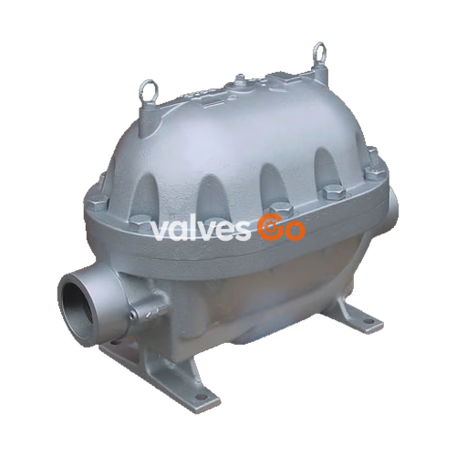
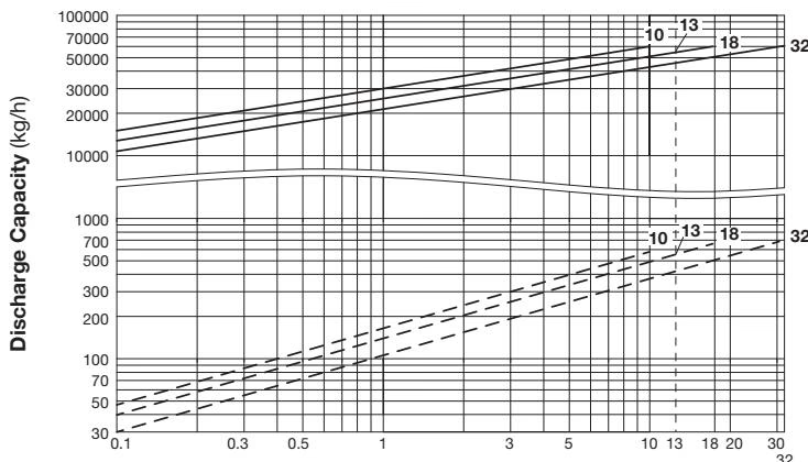
TLV JL14-X and JLH14-X are extremely durable, inline-repairable, high-capacity float steam traps with thermostatic air venting, designed for large process or heating equipment. The series includes the cast iron JL14-X and cast steel JLH14-X, capable of handling maximum operating pressures of up to 32 barg and temperatures up to 240 °C (or 400 °C with the optional bimetal air vent unit).
| Model | JL14-X | JLH14-X |
|---|---|---|
| Connection | Screwed, Flanged | Screwed, Socket Welded, Flanged |
| Size / DN | 3", DN 80 | 3", DN 80 |
| Maximum Operating Pressure (PMO) | 10, 13 barg | 10, 18, 32 barg |
| Maximum Differential Pressure (ΔPMX) | 10, 13 bar | 10, 18, 32 bar |
| Maximum Operating Temperature (TMO) | 200 °C | 240 °C (400 °C optional bimetal) |
WARNING
To avoid abnormal operation, accidents or serious injury, DO NOT use this product outside of the specification range. Local regulations may restrict the use of this product to below the conditions quoted.
| Size | Category | CE marking |
|---|---|---|
| DN 80 | II | With CE marking and Declaration of Conformity |
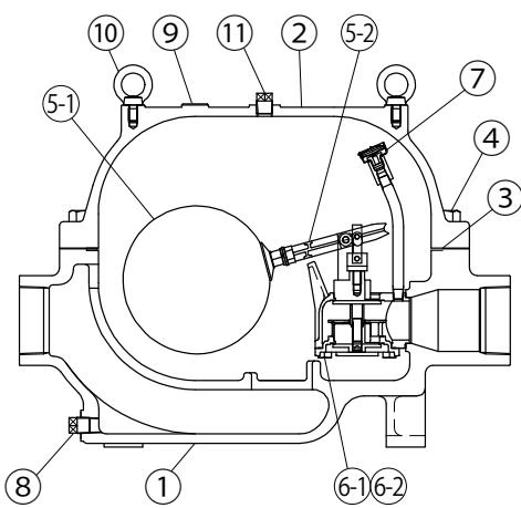
| No. | Description | Material | DIN | ASTM/AISI |
|---|---|---|---|---|
| 1 | Body (JL14-X) | Cast Iron FC250 | 0.6025 | A126 Cl. B |
| 1 | Body (JLH14-X) | Cast Steel A216 Gr. WCB | 1.0619 | - |
| 2 | Cover (JL14-X) | Cast Iron FC250 | 0.6025 | A126 Cl. B |
| 2 | Cover (JLH14-X) | Cast Steel A216 Gr. WCB | 1.0619 | - |
| 3 | Cover Gasket | Graphite/Stainless Steel SUS316L | - / 1.4404 | - / AISI316L |
| 5 | Float / Lever Unit | Stainless Steel SUS316L / Cast Stainl. Steel A351 Gr. CF8 | 1.4404 / 1.4312 | AISI316L / - |
| 6 | Trap Unit (Main Valve Unit) | Stainless Steel SUS304 / Cast Stainl. Steel A743 Gr. CA40 | 1.4301 / 1.4027 | AISI304 / - |
| 7 | Air Vent Unit | Stainless Steel SUS304/420F | 1.4301 / 1.4028 | AISI304 / 420F |
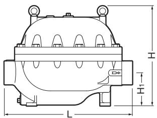
Screwed Dimensions (mm)
| Size | L | H | H1 | W | Weight (kg) |
|---|---|---|---|---|---|
| 3" | 635 | 490 | 163 | 350 | 107 [110] |
Note: [ ] indicates JLH14-X.
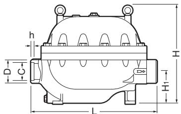
Flanged Dimensions (mm)
| DN | L (DIN 2501 PN16) | L (ASME Class 150RF) | H | H1 | W | Weight (kg) |
|---|---|---|---|---|---|---|
| 80 | 766 | 766 | 490 | 163 | 350 | 121 [124] |
DANGER
DO NOT use this product under conditions that exceed maximum differential pressure, as condensate backup will occur!
INFO
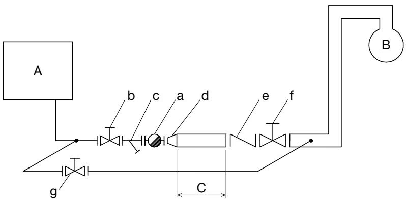
Sample Installation Requirements:




