


PN16

TLV SS3N and SS3V compact, maintenance-free stainless steel free float steam traps with thermostatic air venting for steam mains and tracer lines.
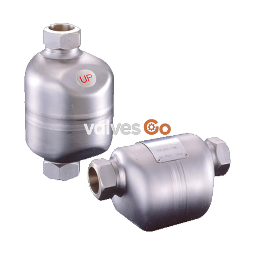
The TLV SS3N and SS3V are compact, maintenance-free, all-stainless steel free float steam traps with a bimetal thermostatic air vent. They are suitable for a wide range of small to medium capacity applications up to 21 barg (or 4.6 MPaG for related series), such as steam mains, tracer lines, and process heaters. The traps discharge condensate continuously and automatically at a temperature slightly lower than the saturation temperature.
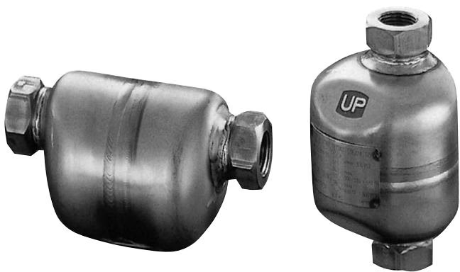
| Model | SS3N | SS3V |
|---|---|---|
| Installation | Horizontal | Vertical |
| Connection | Screwed, Socket Welded, Flanged | Screwed, Socket Welded, Flanged |
| Size | 1/2", 3/4", 1" / DN 15, 20, 25 | 1/2", 3/4", 1" / DN 15, 20, 25 |
| Orifice No. | 5, 10, 21 | 5, 10, 21 |
| Max. Operating Pressure (PMO) | 5, 10, 21 barg | 5, 10, 21 barg |
| Max. Differential Pressure (ΔPMX) | 5, 10, 21 bar | 5, 10, 21 bar |
| Max. Operating Temperature (TMO) | 400 °C | 400 °C |
WARNING
To avoid abnormal operation, accidents, or serious injury, DO NOT use this product outside of the specification range. Local regulations may restrict the use of this product to below the conditions quoted. DO NOT use this product under conditions that exceed maximum differential pressure, as condensate backup will occur.
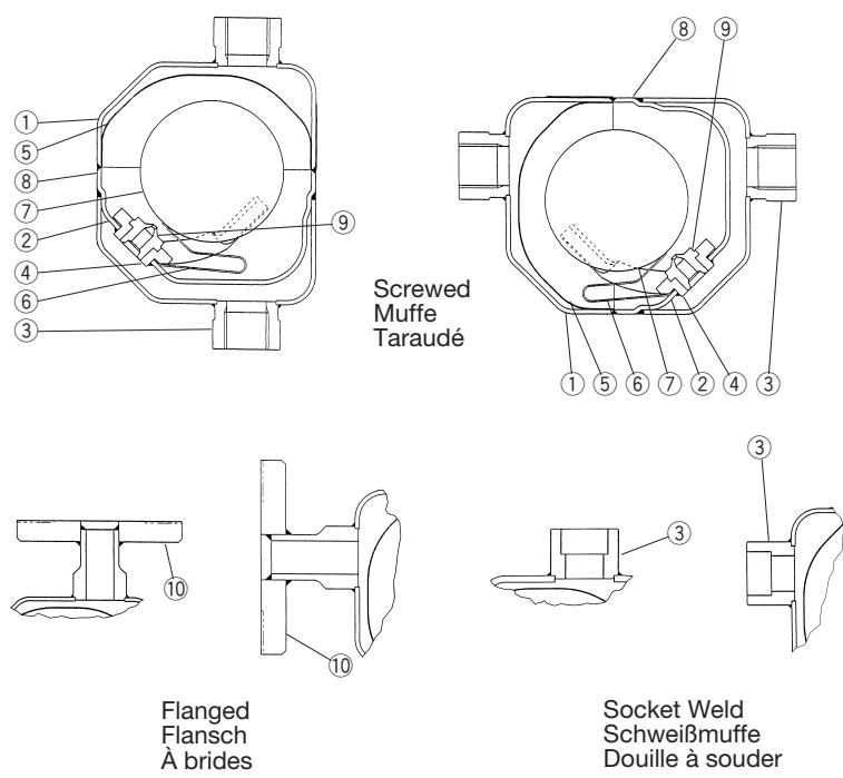
| No. | Description | Material | DIN Equivalent | ASTM/AISI Equivalent |
|---|---|---|---|---|
| 1 | Body | Stainless Steel A240 Type 316L | 1.4404 | — |
| 2 | Inner Cover | Stainless Steel A240 Type 316L | 1.4404 | — |
| 3 | Socket | Cast Stainless Steel A351 Gr.CF8 | 1.4312 | — |
| 4 | Float Guide | Cast Stainless Steel A351 Gr.CF3M | 1.4435 | — |
| 5 | Screen | Stainless Steel SUS304 | 1.4301 | AISI304 |
| 6 | Air Vent Strip | Bimetal | — | — |
| 7 | Float | Stainless Steel SUS316L | 1.4404 | AISI316L |
| 8 | Nameplate | Stainless Steel SUS304 | 1.4301 | AISI304 |
| 10 | Flange | Cast Stainless Steel A351 Gr.CF8 | 1.4312 | — |
DANGER
NEVER apply direct heat to the float. The float may explode due to increased internal pressure, causing accidents leading to serious injury or damage to property and equipment.
Installation Guidelines
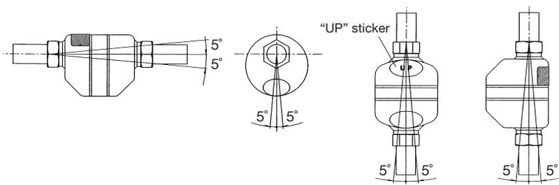
If the expected performance is unachievable after installation, check the following points:
| Problem | Cause | Corrective Measures |
|---|---|---|
| Condensate is not discharged | Pressure exceeds maximum operating pressure | Replace trap with appropriately rated model or reduce steam pressure |
| Pipelines upstream or downstream are clogged | Clean pipelines | |
| Poor discharge of condensate | Pipelines upstream or downstream are clogged | Clean pipelines |
| Trap capacity is too small | Replace with larger trap | |
| Steam leakage or blow-off | Improper trap installation (above max. allowable inclination angle) | Correct trap installation |
| Severe vibration of trap | Reinforce trap piping supports |
An insulation cover (glass mat/glass fiber cloth) is available as an option for the SS3N and SS3V to reduce heat loss.
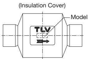
| Model | Applicable Steam Trap | L (mm) | D (mm) | W (mm) | H (mm) |
|---|---|---|---|---|---|
| RK4 | SS3N / SS3V | 160 | 45 | 90 | 100 |




