All-Stainless Steel Material

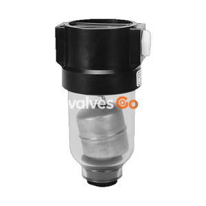
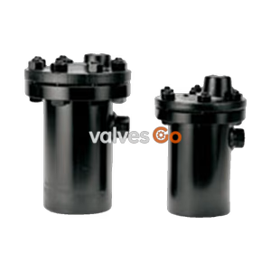
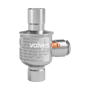
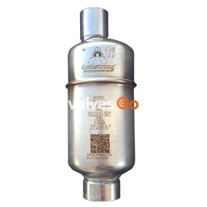
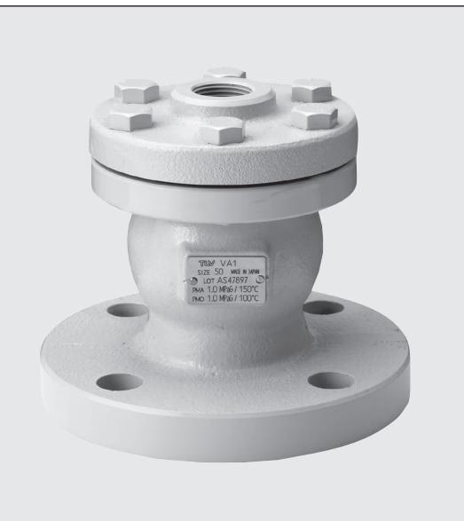
TLV VA1 rapid initial air vent for water systems. Features a float-type mechanical valve, 1.0 MPaG max operating pressure, and 100 °C max temperature. Acts as a vacuum breaker.
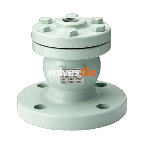
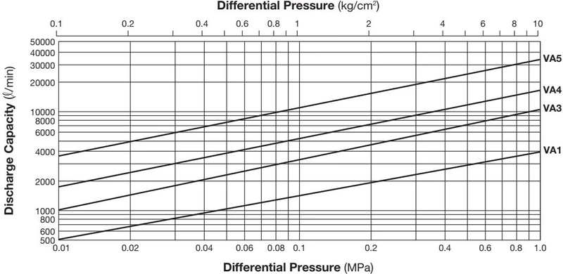
The TLV VA1 is a float-type mechanical rapid initial air vent designed for water piping systems. It rapidly vents air at start-up for moderate to hot water applications and can also serve as a vacuum breaker after venting the initial air. The VA series includes models VA1, VA3, VA4, and VA5, accommodating various connection sizes and capacities.
INFO
Once the valve closes after discharging initial air, it will not open again, even if air accumulates inside the product, until the internal pressure drops to near atmospheric pressure. If air is expected to accumulate in the piping during operation, use together with an automatic air vent.
| Model | VA1 | VA3 | VA4 | VA5 |
|---|---|---|---|---|
| Connection Inlet | Flanged | Flanged | Flanged | Flanged |
| Connection Outlet | Screwed | Screwed | Flanged | Flanged |
| Size Inlet (mm) | 50 | 80 | 100 | 150 |
| Size Outlet (mm) | 20 | 32 | 65 | 100 |
| Maximum Operating Pressure (MPaG) PMO | 1.0 | 1.0 | 1.0 | 1.0 |
| Minimum Operating Pressure (MPaG) | 0.01 | 0.01 | 0.01 | 0.01 |
| Maximum Operating Temperature (°C) TMO | 100 | 100 | 100 | 100 |
| Applicable Fluid | Water | Water | Water | Water |
Do not use for toxic, flammable or otherwise hazardous fluids.Maximum Allowable Pressure (PMA): 1.0 MPaGMaximum Allowable Temperature (TMA): 150 °C
| No. | Description | Material | JIS | ASTM/AISI |
|---|---|---|---|---|
| 1 | Body | Cast Iron | FC250 | A126 Cl.B |
| 2 | Cover | Cast Iron | FC250 | A126 Cl.B |
| 3 | Float | Stainless Steel | SUS316L | AISI 316L |
| 4 | Cover Gasket | Fiber-Rubber Compound | - | - |
| 5 | Cover Bolt | Carbon Steel | SS400 | A307 Gr.B |
| 6 | Valve Seat | Nitrile Rubber | NBR | D2000BF |
| 7 | Valve Seat Retainer (VA1) | Brass | C3604 | B16 C36000 |
| 7 | Valve Seat Retainer (VA3-5) | Bronze | CAC407 | B584 C92200 |
| 8 | Set Screw | Brass | C3604 | B16 C36000 |
| 9 | Float Guide | Bronze | CAC407 | B584 C92200 |
| 10 | Snap Ring | Stainless Steel | SUS304 | AISI 304 |
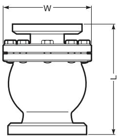
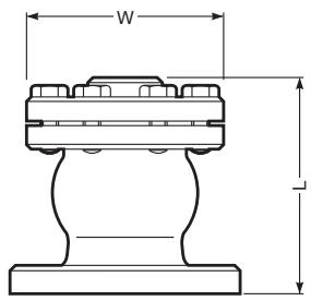
| Model | Size Inlet | Size Outlet | L (125FF) | L (150RF) | φW | Weight (kg) |
|---|---|---|---|---|---|---|
| VA1 | 50 | 20 | 126 | 130 | 110 | 5.1 |
| VA3 | 80 | 32 | 170 | 174 | 145 | 9.5 |
| VA4 | 100 | 65 | 297 | 301 | 235 | 34 |
| VA5 | 150 | 100 | 447 | 447 | 335 | 72 |
(Dimensions in mm. Weight is for Class 125 FF.)
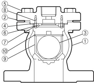
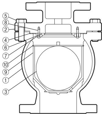
| No. | Part Name | No. | Part Name |
|---|---|---|---|
| 1 | Body | 8 | Set Screw |
| 2 | Cover | 9 | Float Guide |
| 3 | Float | 10 | Snap Ring |
| 4 | Cover Gasket | 11 | Union (VAS only) |
| 5 | Cover Bolt | 12 | Cap Nut (VAS only) |
| 6 | Valve Seat | 13 | Valve Seat Gasket |
| 7 | Valve Seat Holder / Retainer | 14 | Union Gasket (VAS only) |
WARNING
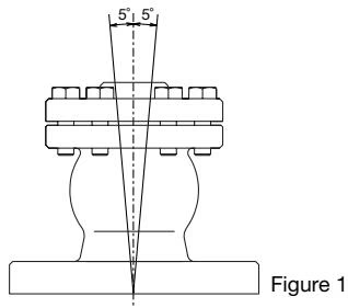
Visual inspections should be carried out periodically to determine whether the rapid initial air vent is operating properly or has failed. Operational inspections should be performed at least twice per year.
DANGER
NEVER apply direct heat to the float. The float may explode due to increased internal pressure, causing accidents leading to serious injury or property and equipment damage.
Parts Inspection Procedure:
| Problem | Cause | Remedy |
|---|---|---|
| No initial air discharged or discharge is poor (blocked) | Air is not reaching the vent because the liquid in the piping is not being displaced by air | Correct the inlet piping (Inner diameter should be at least 16mm) |
| Valve seat is clogged | Clean valve seat | |
| Inlet or outlet piping is clogged | Clean piping | |
| Liquid leaks when valve is closed | Build-up on the surface of the valve seat or the valve seat is damaged | Clean or replace with new valve seat |
| Float is dirty, coated with a film, or is deformed | Clean or replace with new float | |
| Improper installation | Correct the installation | |
| Valve does not close, and liquid spurts out | Liquid is inside the float | Replace with new float |
| Specific gravity of the liquid is not suitable for this product | Select a product with suitable specifications for the operating conditions |
Explore similar products in our catalog