Lift Type

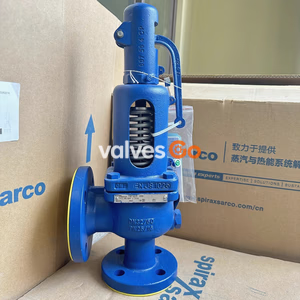
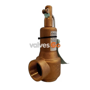
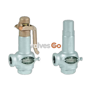
Yoshitake AL-280 closed type relief valve with dashpot structure, designed for continuous pressure control of pumps with high pulsation. Suitable for water and oil.
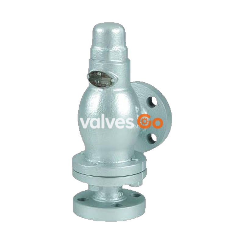
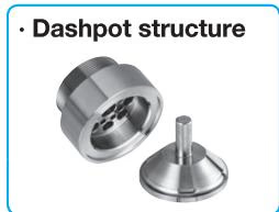
Yoshitake AL-280 relief valve is a closed type relief valve exclusive for the pressure control of pumps with high pulsation pressure or large pressure fluctuation. The trim parts (valve and valve seat) feature a dashpot structure designed to continuously discharge liquid against its setting pressure change without popping, preventing the relief valve from chattering and hunting. Stainless steel with excellent corrosion resistance is used for the adjusting spring.
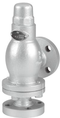
| Structure | Closed type |
|---|---|
| Application | Cold and hot water, Oil (heavy oil A, heavy oil B, kerosene), Non dangerous fluid (Less than 20 cst) |
| Working pressure | 0.05-1.0 MPa |
| Working temperature | 5~120°C |
| Material | Spring case: Ductile cast iron Valve, valve seat: Stainless steel Adjusting spring: Stainless steel |
| Connection | JIS 10K FF flanged |
INFO
Please refer to the flow rate charts for set pressure range.
| Nominal Size | L | H | H1 | D | C | t | n-h | Weight (kg) |
|---|---|---|---|---|---|---|---|---|
| 15A | 90 | 245 | 108 | 95 | 70 | 18 | 4-15 | 4.7 |
| 20A | 90 | 245 | 108 | 100 | 75 | 18 | 4-15 | 5.0 |
| 25A | 90 | 245 | 108 | 125 | 90 | 18 | 4-19 | 6.2 |
| 32A | 91 | 285 | 115 | 135 | 100 | 20 | 4-19 | 8.6 |
| 40A | 91 | 285 | 115 | 140 | 105 | 20 | 4-19 | 8.8 |
| 50A | 105 | 331 | 132 | 155 | 120 | 20 | 4-19 | 13.0 |
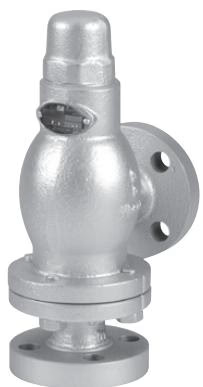
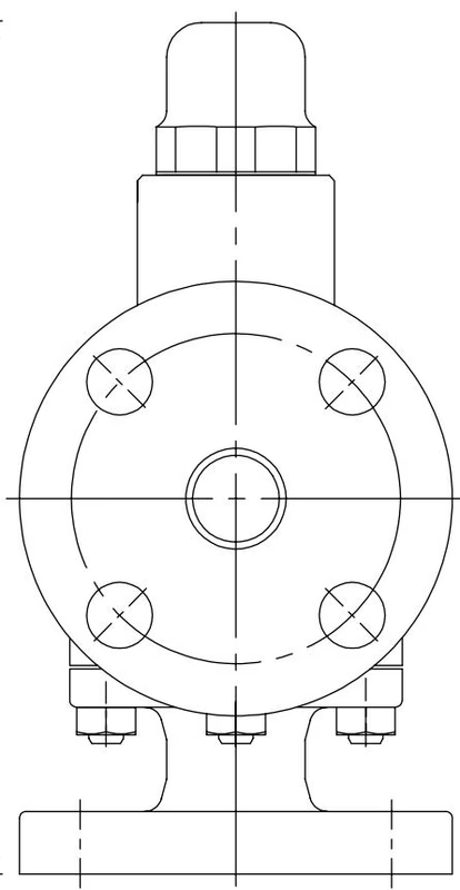
| No | Name of Parts | Material |
|---|---|---|
| 1 | Body | Ductile Cast Iron (FCD450) |
| 2 | Spring Case | Ductile Cast Iron (FCD450) |
| 3 | Valve Seat | Stainless Steel (SUS304) |
| 4 | Valve | Stainless Steel (SUS304) |
| 5 | Spindle | Brass (C3604) |
| 6 | Spring | Stainless Steel (SUS304) |
| 7 | Lower Spring Plate | Brass (C3604) |
| 8 | Upper Spring Plate | Brass (C3604) |
| 9 | Adjusting Screw | Brass (C3604) |
| 10 | Lock Nut | Brass (C3604) |
| 11 | Cap | Cast Iron (FC200) |
| 12 | Gasket | Non-Asbestos |
| 13 | Gasket | Non-Asbestos |
| 14 | Stud Bolt | Rolled Steel (SS400) |
| 15 | Nut | Rolled Steel (SS400) |
| 16 | Name Plate | Stainless Steel (SUS304) |
| 17 | Rivet | Carbon Steel (S15C) |
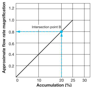
The flow rate to each nominal size when the accumulation (overpressure to the set pressure) is 25% is as shown in Fig. 1. See Fig. 2 when the accumulation is less than 25%.
Fig. 1: Nominal size selection chart
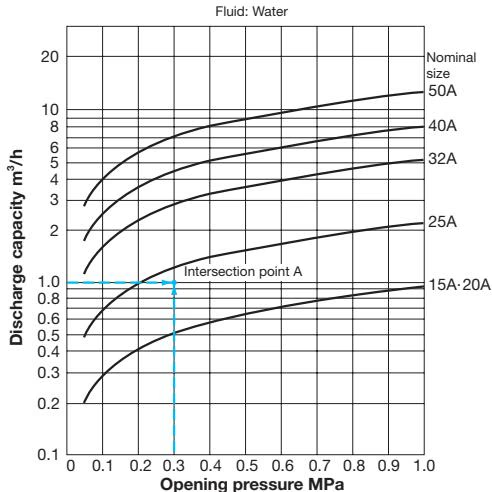
Fig. 2: Approximate flow rate magnification
When the accumulation is less than 25%, select an approximate flow rate magnification matching the accumulation based on this chart, and multiply the flow rate at 25% accumulation by the selected magnification.
Example 1: Nominal Size Selection To select a nominal size when the working conditions are pressure: 0.3 MPa and discharge capacity: 1.0 m³/h, first find intersection point A of the pressure of 0.3 MPa on the horizontal axis and the discharge capacity of 1.0 m³/h on the vertical axis in Fig. 1. Since intersection point A lies between the curve of nominal sizes 15A·20A and the curve of nominal size 25A, select the larger one, 25A.
Example 2: Flow Rate Calculation To obtain the flow rate when the working conditions are nominal size: 25A, setting pressure: 0.1 MPa, and accumulation: 20%, first find the flow rate at an accumulation of 25% in Fig. 1. Then, mark intersection point B of the accumulation of 20% and the diagonal straight line in Fig. 2. Trace horizontally to the left from this intersection point B, and reach the point of 0.8 on the axis of approximate flow rate magnification.
Flow rate is given in m³/h.
| Nominal size | Flow area (mm²) | 0.05 MPa | 0.1 MPa | 0.2 MPa | 0.3 MPa | 0.4 MPa | 0.5 MPa | 0.6 MPa | 0.7 MPa | 0.8 MPa | 0.9 MPa | 1.0 MPa |
|---|---|---|---|---|---|---|---|---|---|---|---|---|
| 15A·20A | 16.7 | 0.20 | 0.29 | 0.41 | 0.51 | 0.59 | 0.66 | 0.72 | 0.78 | 0.83 | 0.88 | 0.93 |
| 25A | 39.2 | 0.49 | 0.69 | 0.98 | 1.20 | 1.38 | 1.54 | 1.69 | 1.83 | 1.96 | 2.07 | 2.19 |
| 32A | 91.9 | 1.14 | 1.62 | 2.29 | 2.81 | 3.24 | 3.63 | 3.97 | 4.29 | 4.59 | 4.87 | 5.13 |
| 40A | 143.6 | 1.79 | 2.53 | 3.58 | 4.39 | 5.07 | 5.67 | 6.21 | 6.71 | 7.17 | 7.61 | 8.02 |
| 50A | 224.3 | 2.80 | 3.96 | 5.60 | 6.86 | 7.92 | 8.86 | 9.71 | 10.49 | 11.21 | 11.89 | 12.53 |
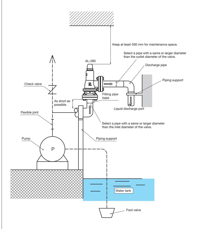
Select a pipe with a same or larger diameter than the outlet diameter of the valve.
Yoshitake Safety Valves / Relief Valves
AF and AL series safety and relief valves for overpressure protection of steam, water, and air equipment.