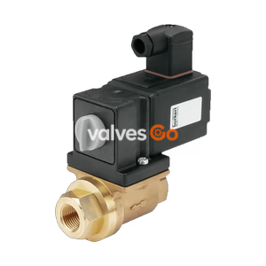
PN16

Yoshitake DP-100-D and DP-100F-D pilot-operated piston type solenoid valves with DC 24V coil. Features stainless steel construction, suitable for steam, air, water, and gas up to 1.0 MPa.
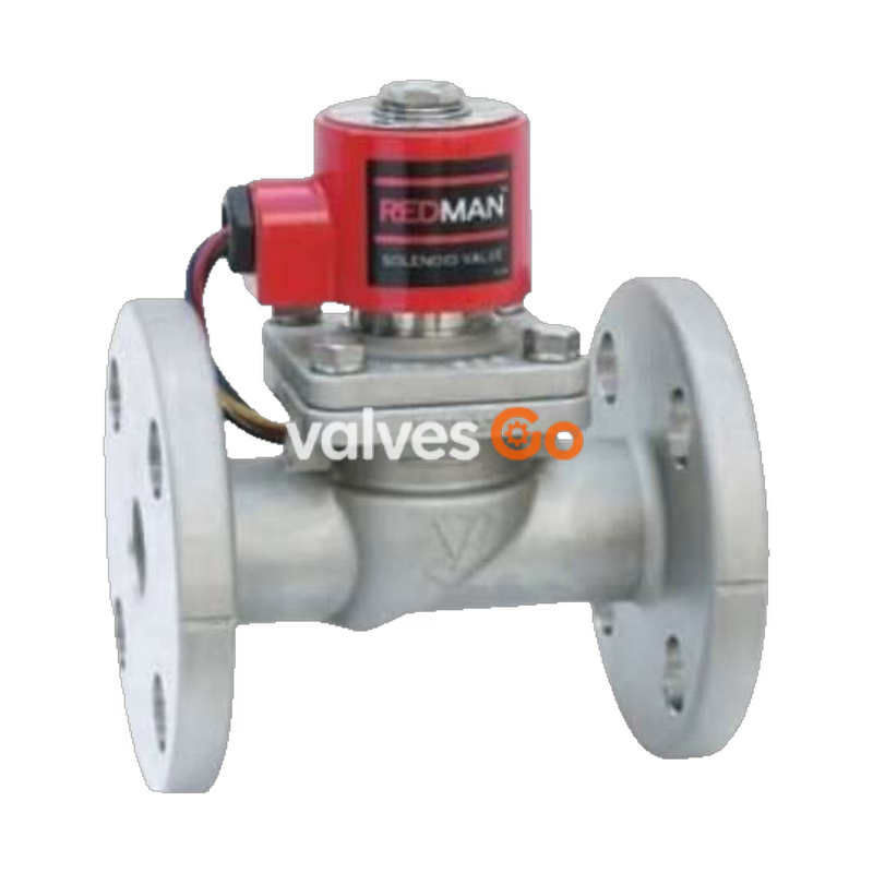
Yoshitake DP-100-D and DP-100F-D are pilot-operated piston type solenoid valves equipped with a DC 24V coil. Designed with a robust stainless steel (SCS14A) body and piston, and a PTFE valve disc, these normally closed valves provide reliable zero-leakage performance under standard conditions. They are highly versatile, suitable for a wide range of fluids including steam, air, cold and hot water, nitrogen gas, dry carbon dioxide, argon gas, and light oils (20 cSt or less).
These valves support both horizontal and vertical installation (within 90 degrees from the upward position of the coil) and operate efficiently across a pressure range of 0 to 1.0 MPa. The DP-100-D features a JIS Rc screwed connection, while the DP-100F-D offers a JIS 10K FF flanged connection.
 DP-100-D (Screwed type)
 DP-100F-D (Flanged type)
| Model | DP-100-D | DP-100F-D |
|---|---|---|
| Nominal size | 10A-50A | 15A-65A |
| Structure | Pilot-operated piston type | Pilot-operated piston type |
| Application | Steam, Air, Cold and hot water, N2 gas, CO2 gas (dry), Ar gas, Oil (20 cSt or less) | Steam, Air, Cold and hot water, N2 gas, CO2 gas (dry), Ar gas, Oil (20 cSt or less) |
| Working pressure | 0-1.0 MPa (unusable under vacuum) | 0-1.0 MPa (unusable under vacuum) |
| Min. differential pressure | 0 MPa (0.03 MPa or more is required for vertical installation) | 0 MPa (0.03 MPa or more is required for vertical installation) |
| Allowable valve seat leakage | 50 mL/min under standard conditions (at air pressure of 0.6 MPa) | 50 mL/min under standard conditions (at air pressure of 0.6 MPa) |
| Temperature range | 5-180°C (no freeze condition) | 5-180°C (no freeze condition) |
| Ambient temperature | 50°C or less (no freeze condition) | 50°C or less (no freeze condition) |
| Installation posture | Vertical or horizontal installation (within 90 degrees from upward position of the coil) | Vertical or horizontal installation (within 90 degrees from upward position of the coil) |
| Material (Body/Piston) | Stainless steel (SCS14A) | Stainless steel (SCS14A) |
| Material (Valve disc) | PTFE | PTFE |
| Connection | JIS Rc screwed | JIS 10K FF flanged |
| Item | Specification |
|---|---|
| Rated voltage | DC 24 V |
| Nominal size | 10-25A / 32-65A |
| Rated current | 1.34 A (10-25A) / 1.14 A (32-65A) |
| Allowable fluctuation | Rated voltage -5% to +10% |
| Insulation class | Insulation class H |
| Protective structure | Dust tight, Splash proof |
| Ingress protection code | IP64 (JIS C0920) |
| Insulation resistance | 50 MΩ and more / 500 V megger |
| Withstand voltage test | 1500 V/min |
INFO
Available with a terminal box upon request.
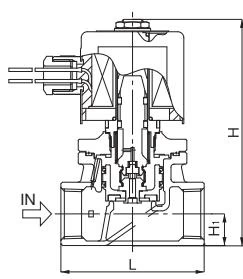
| Nominal size | d | L | H1 | H | Weight (kg) |
|---|---|---|---|---|---|
| 10A | Rc 3/8 | 70 | 14.5 | 143 | 2.2 |
| 15A | Rc 1/2 | 70 | 14.5 | 143 | 2.2 |
| 20A | Rc 3/4 | 80 | 17.5 | 147 | 2.3 |
| 25A | Rc 1 | 95 | 21.0 | 151 | 2.7 |
| 32A | Rc 1-1/4 | 110 | 26.0 | 194 | 4.3 |
| 40A | Rc 1-1/2 | 120 | 29.5 | 200 | 5.2 |
| 50A | Rc 2 | 140 | 36.5 | 209 | 6.8 |
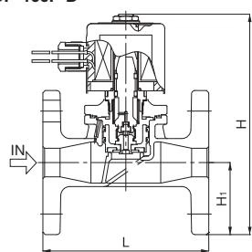
| Nominal size | d | L | H1 | H | Weight (kg) |
|---|---|---|---|---|---|
| 15A | 15 | 120 | 47.5 | 177 | 3.5 |
| 20A | 20 | 130 | 50.0 | 180 | 4.0 |
| 25A | 25 | 145 | 62.5 | 193 | 5.3 |
| 32A | 32 | 160 | 67.5 | 235 | 8.1 |
| 40A | 40 | 170 | 70.0 | 241 | 9.2 |
| 50A | 50 | 195 | 77.5 | 250 | 11.7 |
| 65A | 50 | 198 | 87.5 | 260 | 13.5 |
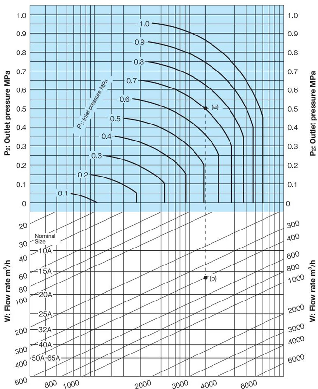
How to use the chart: When selecting the nominal size of a solenoid valve whose inlet pressure (P1), outlet pressure (P2), and steam (saturated steam) flow rate (W) are 0.7 MPa, 0.5 MPa, and 400 kg/h, respectively, first find intersection point (a) of P1 = 0.7 MPa and P2 = 0.5 MPa. Trace down vertically from this intersection point (a) to find intersection point (b) with W = 400 kg/h. Since this intersection point (b) lies between nominal sizes 15A and 20A, select the larger one, 20A.
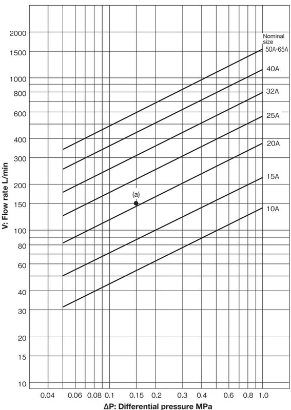
How to use the chart: When selecting the nominal size of a solenoid valve whose inlet pressure (P1), outlet pressure (P2), and flow rate (V) are 0.5 MPa, 0.35 MPa, and 150 L/min, respectively, first find intersection point (a) of the differential pressure before and after the valve [ΔP = 0.5 - 0.35 = 0.15 MPa] and V = 150 L/min. Since this intersection point (a) lies between nominal sizes 20A and 25A, select the larger one, 25A.
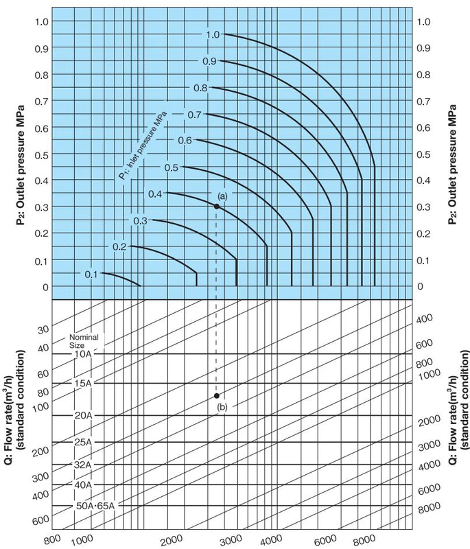
How to use the chart: When selecting the nominal size of a solenoid valve whose inlet pressure (P1), outlet pressure (P2), and air (20˚C) flow rate (Q) are 0.4 MPa, 0.3 MPa, and 300 m³/h (standard condition), respectively, first find intersection point (a) of P1 = 0.4 MPa and P2 = 0.3 MPa. Trace down vertically from this intersection point (a) to find intersection point (b) with Q = 300 m³/h (standard condition). Since this intersection point (b) lies between nominal sizes 15A and 20A, select the larger one, 20A.
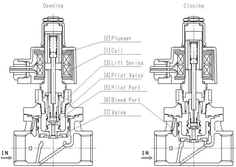
When the power is turned ON, the coil [1] is excited and pulls up the plunger [2], to open the pilot valve [4]. Next, the pressure at the upper part of the valve [7] drops since it flows to the outlet through the pilot port [5]. The valve [7] is then lifted up to open position by the inlet pressure.
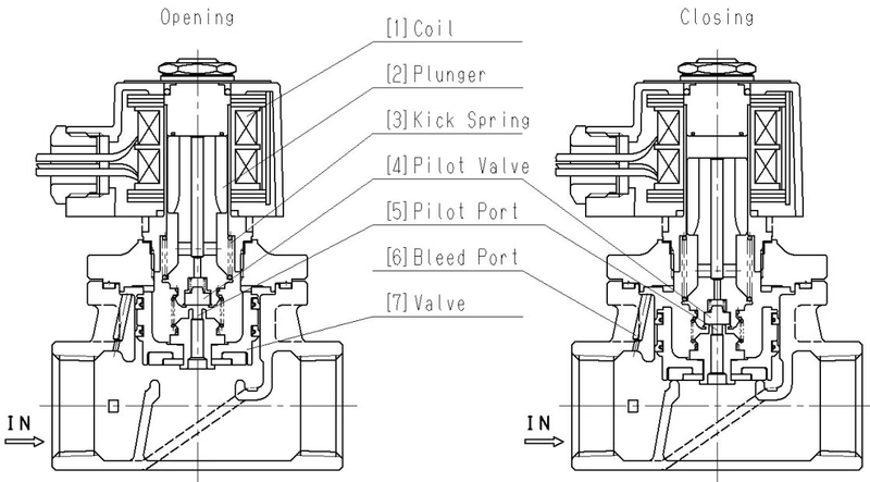
When the power is turned OFF, the coil [1] excitation is canceled and the plunger [2] drops down by force of the kick spring [3], to close the pilot valve [4]. The pressure at the upper part of the valve [7] rises due to the incoming inlet pressure from the bleed port [6] which is communicated with the inlet. With the support of the kick spring [3], this makes the valve [7] pushed down to closed position.
WARNING
Electric wiring work must be done by experienced professional.
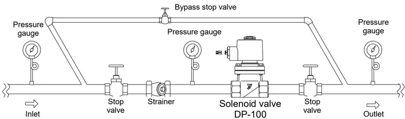
Piping Recommendations
WARNING
Disassembly and maintenance must be done by experienced professional or valve manufacturer.
Replace the following parts to maintain optimal performance:
| Trouble | Cause | Remedy |
|---|---|---|
| The valve does not open (Fluid does not flow) | 1. Strainer at inlet is clogged. 2. Plunger assy is stuck with foreign substances. 3. Pilot valve seat portion gets stuck. 4. Fluid pressure exceeds specified working pressure. 5. Fluid viscosity exceeds 20 cSt. | 1. Clean the strainer. 2. Disassemble and remove foreign substances. 3. Replace the valve complete set. 4. Adjust fluid pressure. 5. Adjust fluid viscosity. |
| The valve does not close (Fluid flow does not stop) | 1. Plunger assy or valve seat is stuck or damaged. 2. Plunger assy is stuck with foreign substances. 3. Installed in the opposite direction. 4. Bypass stop valve is kept open. 5. Differential pressure is less than 0.03 MPa (when coil is sideways). | 1. Disassemble and remove foreign substances. Replace if damaged. 2. Disassemble and remove foreign substances. 3. Reinstall correctly. 4. Close bypass stop valve. 5. Adjust differential pressure or install vertically. |
| External leakage is observed | 1. Pipe is loosened. 2. Hexagon head bolt is loosened. 3. Cover gasket is damaged. | 1. Replace the cover complete set. 2. Retighten with specified torque. 3. Replace the cover gasket. |
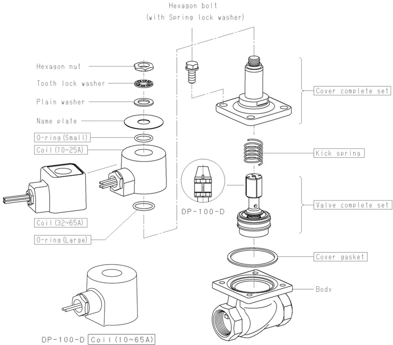
The parts name shown in the rectangle boxes are available as consumable supply.Apply lubricant agent (Recommendation: SOLVEST No.110 paste, STT Inc.) to the threaded area.
Yoshitake Actuation & Positioners / Solenoid
DD and DP series solenoid valves for automatic fluid shutoff and interlocking control.
Explore similar products in our catalog