PN16

Yoshitake DP-200F-N pilot-operated solenoid valve with JIS 10K FF flanged connection and JWWA approval. Features NBR diaphragm, NPb-treated bronze body, zero leakage, and AC coil for water, air, and gas up to 1.0 MPa.
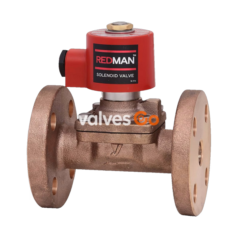
Yoshitake DP-200F-N pilot-operated solenoid valve is designed for automatic on-off control of cold and hot water, air, N2 gas, CO2 gas (dry), Ar gas, and light oils (20 cSt or less). Featuring a JIS 10K FF flanged connection and a bronze construction with NPb treatment, this normally closed valve integrates an NBR diaphragm to ensure zero leakage. The DP-200F-N complies with the Japanese Water Works Law (JWWA) and accommodates a working pressure range of 0 to 1.0 MPa, making it suitable for a variety of industrial fluid control applications.
INFO
Model DP-200F-N is the JWWA-approved version with flanged connections. Model DP-200-N provides JIS Rc screwed connections with JWWA approval.
| Specification | DP-200F-N (Normally Closed) |
|---|---|
| Structure | Pilot-operated diaphragm type |
| Application | Cold and Hot water, Air, N2 gas, Co2 gas (dry), Ar gas, Oil (20 cSt or less) |
| Working pressure | 0–1.0 MPa (Unusable under vacuum) |
| Min. differential pressure | 0 MPa (0.1 MPa or more is required if the coil set sideways) |
| Allowable valve seat leakage | No (by confirming pressure gauge visually) |
| Temperature range | 5–60°C (no freeze condition) |
| Ambient temperature | 50°C or less (no freeze condition) |
| Installation posture | Vertical or horizontal installation (within 90 degrees from upward position of the coil) |
| Body / Valve Material | Bronze (NPb-treated) |
| Diaphragm Material | NBR |
| Connection | JIS 10K FF flanged |
Note: Available with rubber material FKM for the diaphragm. Max. temperature: 90°C (only for standard DP-200, DP-200F).
| Item | Specification |
|---|---|
| Rated voltage | AC 100/200 V or AC 110/220 V selective type (50/60 Hz common) |
| Allowable fluctuation | Rated voltage –5% to +10% |
| Rated current | 0.42 / 0.21 A (100/200V) or 0.38 / 0.19 A (110/220V) |
| Starting current | 1.64 / 0.82 A (100/200V) or 1.48 / 0.74 A (110/220V) |
| Insulation class | Insulation class H |
| Protective structure | Dust tight, Splash proof (IP64 JIS C0920) |
| Insulation resistance | 50 MΩ and more / 500 V megger |
| Withstand voltage test | 1500 V/min |
| Removing lead wire | Conduit G 1/2 (CTG 16) |
Available with a terminal box (made of plastic).
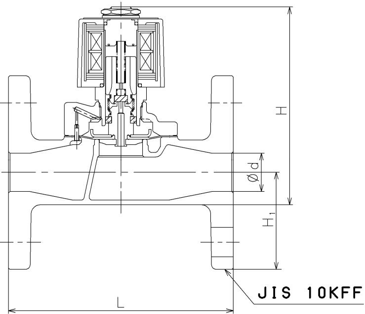
| Nominal Size | d | L | H | H1 | Weight (kg) |
|---|---|---|---|---|---|
| 15A | 15 | 120 | 147 | 47.5 | 2.7 |
| 20A | 20 | 130 | 153 | 50.0 | 3.3 |
| 25A | 25 | 145 | 169 | 62.5 | 4.8 |
| 32A | 32 | 160 | 192 | 67.5 | 6.6 |
| 40A | 40 | 170 | 198 | 70.0 | 7.3 |
| 50A | 50 | 195 | 213 | 77.5 | 10.0 |
(Dimensions in mm)
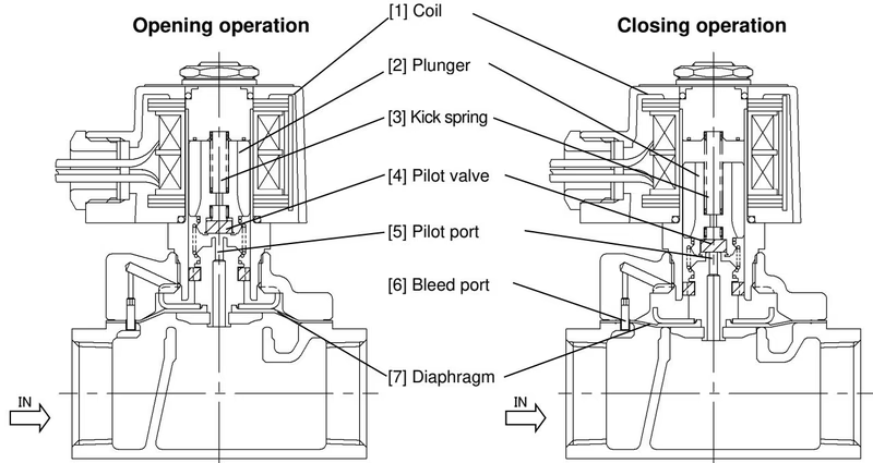
When the power is turned ON, the coil [1] is excited and pulls up the plunger [2], to open the pilot valve [4]. Next, the pressure at the upper part of the diaphragm [7] drops since it flows to the outlet through the pilot port [5]. The diaphragm [7] is then lifted up to the open position by the inlet pressure.
When the power is turned OFF, the coil [1] excitation is canceled and the plunger [2] drops down by the force of the kick spring [3], to close the pilot valve [4]. The pressure at the upper part of the diaphragm [7] rises due to the incoming inlet pressure from the bleed port [6] which is communicated with the inlet. With the support of the kick spring [3], this makes the diaphragm [7] pushed down to the closed position.
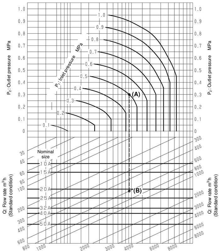
When selecting the nominal size of a solenoid valve whose inlet pressure (P1), outlet pressure (P2), and air (20˚C) flow rate (Q) are 0.5 MPa, 0.3 MPa, and 600 m³/h (standard condition), respectively: first find intersection point (A) of P1 = 0.5 MPa and P2 = 0.3 MPa. Trace down vertically from this intersection point (A) to find intersection point (B) with Q = 600 m³/h. Since this intersection point (B) lies between nominal sizes 20A and 25A, select the larger one, 25A.
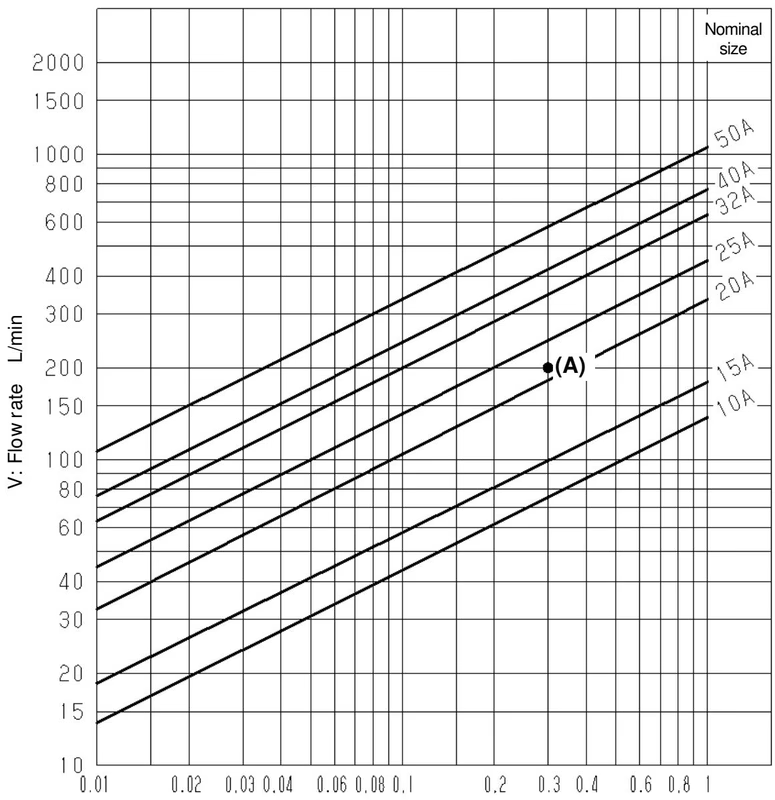
When selecting the nominal size of a solenoid valve whose inlet pressure (P1), outlet pressure (P2), and flow rate (V) are 0.6 MPa, 0.3 MPa, and 200 L/min, respectively: first find intersection point (A) of the differential pressure before and after the valve [∆P = 0.6-0.3 = 0.3 MPa] and V = 200 L/min. Since this intersection point (A) lies between nominal sizes 20A and 25A, select the larger one, 25A.
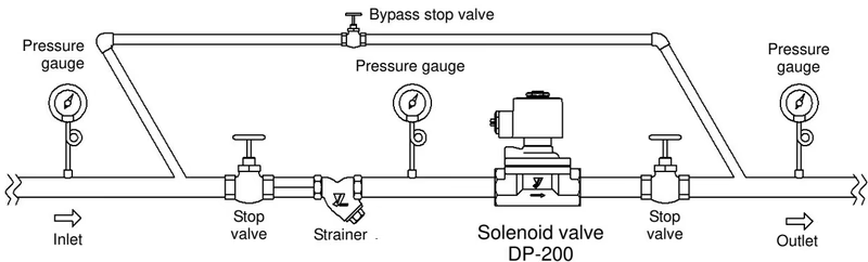
Installation Precautions
Precaution for Operation
Test Working: Before performing test working, close the stop valves at both sides and remove foreign substances by flushing the bypass line. Switch the product on and off a few times without fluid to confirm the plunger's clicking sound. Then lead fluid gradually and confirm normal opening, closing, and zero leakage.
Maintenance: Disassembly and maintenance must be done by an experienced professional. Always confirm that no power is supplied and pressure is completely discharged before disassembling. Conduct daily inspections (verifying on/off operation and checking for outside leakage) to maintain optimal performance.
Yoshitake Actuation & Positioners / Solenoid
DD and DP series solenoid valves for automatic fluid shutoff and interlocking control.
Explore similar products in our catalog