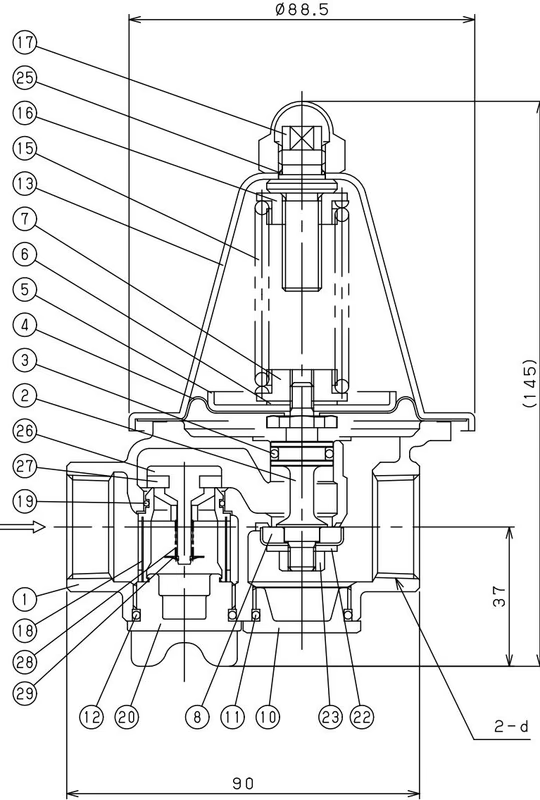
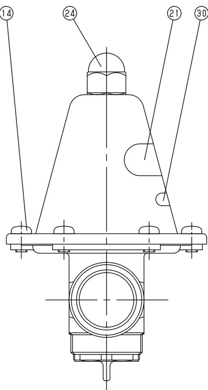
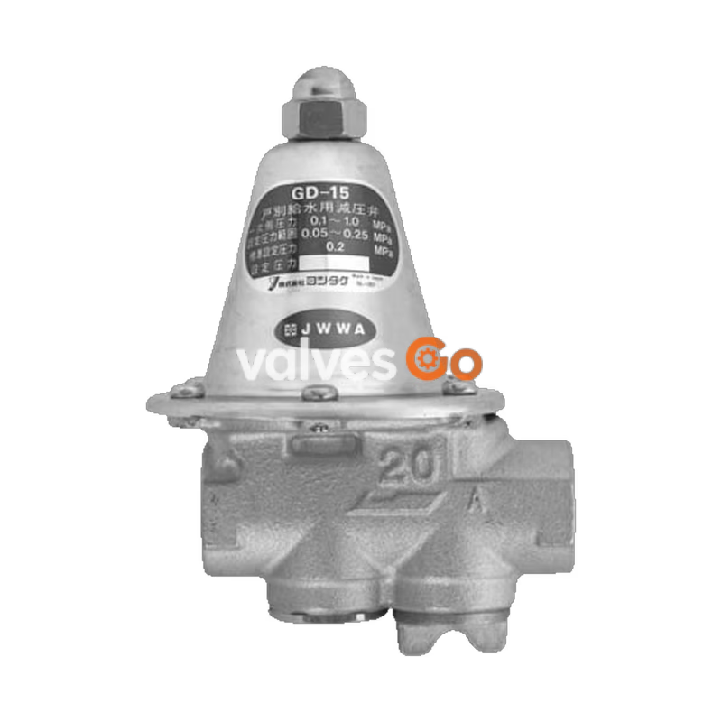
Yoshitake GD-15, 15C are low-noise pressure reducing valves for individual water supply to complex housing. They highly maintain the stable reduced pressure against a variation of supply water pressure. The incorporated strainer and the compact and light weight design ensure easy piping. The GD-15C is equipped with a check valve to prevent back-flow to the main water supplying pipe.
Features
- Removed noise. Can be used even late at night.
- Water supplying pressure has already been adjusted at 0.2 MPa (standard setting), so no need to adjust at sight.
- Pressure balance structure can keep the reduced pressure at a constant level without being affected by inlet pressure.
- Incorporated strainer prevents foreign substances such as dirt, scale and sand from flowing to the outlet side.
- Easy maintenance because strainer and strainer cap are integrated and detachable without any tool.
- Closed structure prevents fluid flowing to the outside even when the diaphragm is damaged or broken.
- Pipes can be installed either horizontally or vertically.
Specifications
| Nominal size | 15A | 20A |
|---|
| Application | City water | City water |
| Inlet pressure | 0.1-1.0 MPa | 0.1-1.0 MPa |
| Reduced pressure | 0.05-0.25 MPa [Standard setting: 0.2 MPa] | 0.05-0.25 MPa [Standard setting: 0.2 MPa] |
| Minimum differential pressure | 0.03 MPa | 0.03 MPa |
| Maximum pressure reduction ratio | 10:1 | 10:1 |
| Minimum adjustable flow rate | 0.5 L/min | 0.5 L/min |
| Working temperature | 5-60°C* | 5-60°C* |
| Rated flow rate | 25 L/min (40 L/min when differential pressure is 0.10 MPa or more) | 30 L/min (50 L/min when differential pressure is 0.10 MPa or more) |
| Material (Body) | Bronze (NPb-treated) | Bronze (NPb-treated) |
| Material (Spindle) | Brass | Brass |
| Material (Valve) | Synthetic rubber | Synthetic rubber |
| Material (Diaphragm) | EPDM (with fabric) | EPDM (with fabric) |
| Connection | JIS Rc screwed | JIS Rc screwed |
| Outlet withstand pressure | 1.2 times of maximum outlet pressure | 1.2 times of maximum outlet pressure |
Notes
- The closing pressure of the check valve for GD-15C is 0.005 MPa or less.
- The strainer is 40 mesh.
- An incombustible material is used for heat insulating material.
- Please contact us for using at hot water supplying side.
Dimensions and Weights
| Nominal size | d | Weights (kg) |
|---|
| 15A | Rc 1/2 | 0.87 |
| 20A | Rc 3/4 | 0.87 |
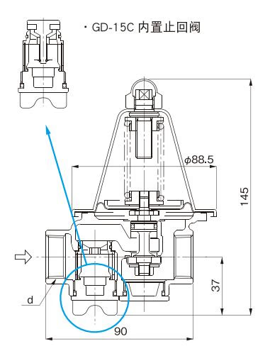
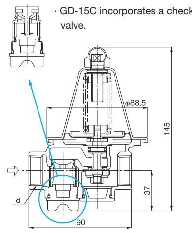
GD-15, 15C Data
Pressure Characteristic Chart
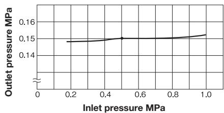 This chart shows variation in reduced pressure when the inlet pressure of 0.5 MPa is changed between 0.18 MPa and 1.0 MPa, while the reduced pressure is set at 0.15 MPa.
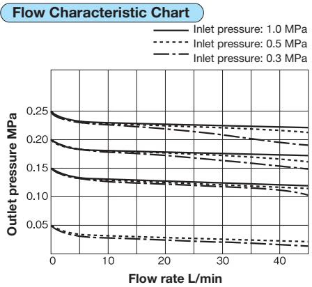
- Distance from the sample valve to the microphone: 15cm
- Back ground noise: 35 db(A)
Precautions During Installation
- Install the valve so as to make the arrow on body points the same direction as flow.
- Pipes can be installed either horizontally or vertically.
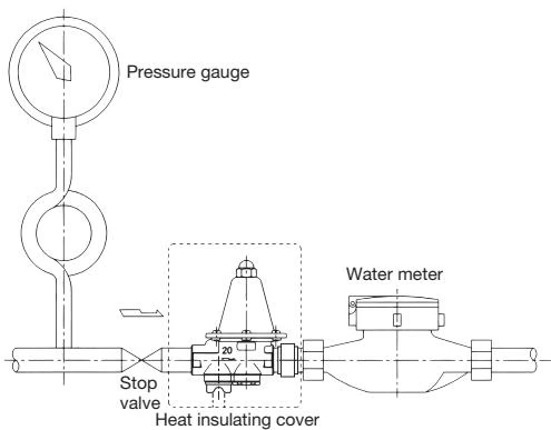
- Maintenance will be easier by installing union joint in front and after the pressure reducing valve.
- Please be sure to remove foreign substances and scales from inside of the piping before connecting the product to the piping.
- Since the pressure has already been set, please do not touch the adjusting screw unless changing the set pressure. Please adjust pressure in the indicated range on the label, when changing the set pressure.
- Please clean up the strainer regularly, because the water supply decrease as foreign substance accumulates inside the strainer. Especially foreign substance accumulates at the first plumbing, so check the strainer soon after starting water supplying.
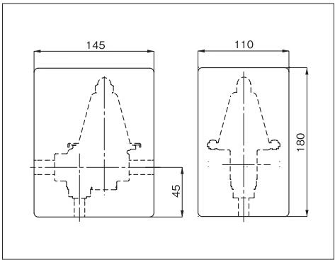
- GD-15 needs 50 mm (GD-15C 55 mm) or more space for checking the strainer.
- Caution when installing Polyvinyl chloride pipe: Synthetic rubber could be attacked by glue of polyvinyl chloride pipe. Please be careful not to flow glue in to the valve.
- It is recommended to use bronze or stainless steel nipples on the outlet side piping of the product because corrosion of steel pipe edge will increase yearly. The rust may clog the sensing port of the product and decreases the water flow.
How to Adjust the Pressure
When adjusting the pressure, please follow to the procedure as follows. Otherwise inappropriate adjustment may cause water hammer or hunting and break important parts.
- Gradually open the inlet side stop valve fully and slightly open the outlet side stop valve to allow a small amount of flow.
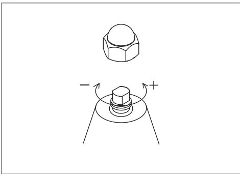
- Remove the cap. Checking the pressure gauge, turn the adjusting screw to adjust the reduced pressure to a desired level.
- The reduced pressure decreases when the adjusting screw is turned clockwise.
- The reduced pressure increases when the adjusting screw is turned counterclockwise.
- Gradually open the outlet side stop valve fully.
- After reduced pressure adjustment, attach the cap.
Piping Example
Parts Diagram