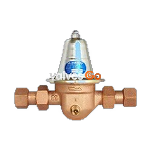
The Yoshitake GD-25GJ-K achieves low-noise water supply as a pressure reducing valve for individual water supply to complex housing. Reduced pressure can be kept highly stable against a variation of supply water pressure. The incorporated strainer and its compact and lightweight design ensure easy handling of piping. The GD-25GJ-L type pressure reducing valve is provided with a built-in anti-corrosion pipe end core for lining steel pipe.
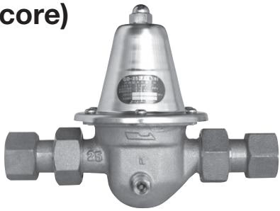
Features of the Tube End Anti-Corrosion Core
- The pipe end core separates the end face of lined steel pipe or threaded ends from the fluid to prevent potential corrosion.
- Fittings such as bronze nipples or anti-corrosion sockets are not required. Plumbing work is simpler and more economical.
- The GD-25GJ-L is equipped with a built-in core.
- It can keep high air-tightness.
Specifications
| Model | GD-25GJ-K | GD-25GJ-L |
|---|
| Nominal size | 25A | 25A |
| Application | City water | City water |
| Inlet pressure | 1.0 MPa or less | 1.0 MPa or less |
| Reduced pressure | (A) 0.05-0.10 MPa [Standard: 0.09 MPa]
(B) 0.10-0.22 MPa [Standard: 0.20 MPa]
(C) 0.20-0.35 MPa [Standard: 0.25 MPa] | (A) 0.05-0.10 MPa [Standard: 0.09 MPa]
(B) 0.10-0.22 MPa [Standard: 0.20 MPa]
(C) 0.20-0.35 MPa [Standard: 0.25 MPa] |
| Minimum differential pressure | 0.02 MPa | 0.02 MPa |
| Maximum pressure reduction ratio | 10:1 | 10:1 |
| Minimum adjustable flow rate | 0.5 L/min | 0.5 L/min |
| Fluid temperature | 5-90℃ | 5-40℃ |
| Rated flow rate | 85 L/min (100 L/min when differential is ≥0.10 MPa) | 85 L/min (100 L/min when differential is ≥0.10 MPa) |
| Body / Valve seat | Cast bronze (NPb-treated) | Cast bronze (NPb-treated) |
| Spindle | Brass | Brass |
| Valve disc / Diaphragm | Synthetic rubber | Synthetic rubber |
| Connection | JIS Rc 1 screwed (union joint) | JIS Rc 1 screwed (union joint) |
| Pressure gauge joint | JIS Rc 1/8 | JIS Rc 1/8 |
- The strainer is 40 mesh.
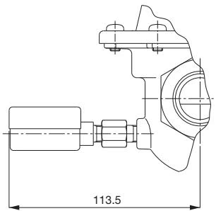
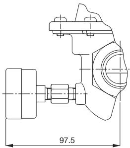
- Available with pressure gauge (type A or type D) as option (for 0.5 MPa). The accuracy of a pressure gauge is ±3% F.S.
- Connect pressure gauge (JIS R1/8) at the site.
- An incombustible material is used for heat insulating material.
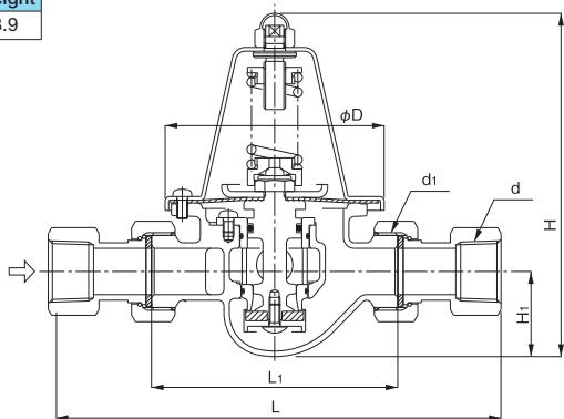
Dimensions and Weights
| d | d1 | L | L1 | H | H1 | D | Weight (kg) |
|---|
| Rc1 | G 1-1/4 | 250 | 136 | 186 | 46 | 121 | 3.9 |
Dimensions with Optional Pressure Gauge
Equipped with the pressure gauge Type A
Equipped with the pressure gauge Type D
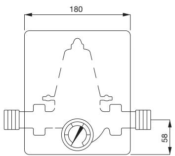
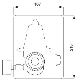
Dimensions of the Heat Insulating Material
Characteristic Charts
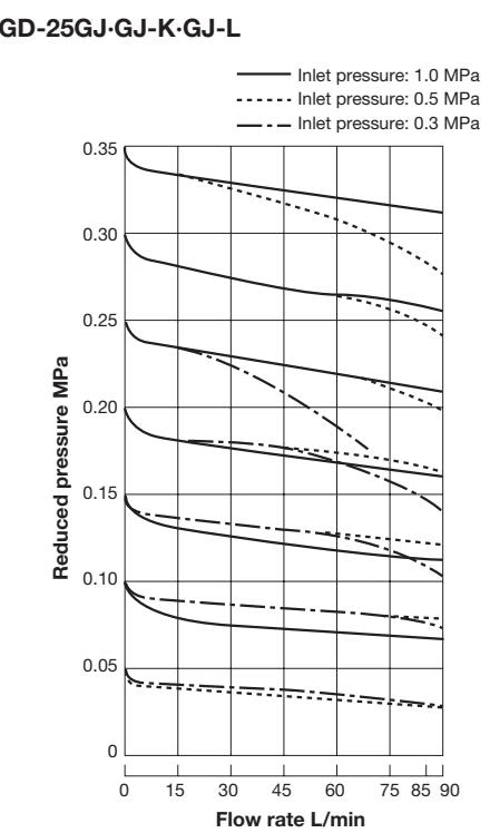
Flow Rate Characteristic Chart
Pressure Characteristic Chart
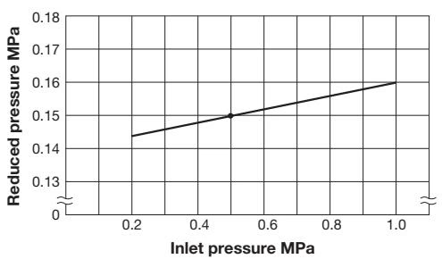
This chart shows variation in reduced pressure when the inlet pressure of 0.5 MPa is changed between 0.2 MPa and 1.0 MPa while the reduced pressure is set at 0.15 MPa.
Notes on Installation
- Horizontal installation or vertical installation to the piping is available.
- Install limiting the dusts, Cl, and sands from the piping.
WARNING
Do not touch the adjusting screw unnecessarily because setting pressure is adjusted to standard setting pressure.
- Please clean up the strainer regularly, because the water supply decreases as foreign substance accumulates inside the strainer. Especially foreign substance accumulates at the first plumbing, so check the strainer soon after starting water supplying. Cleaning requires space of 135mm.
- Caution on piping installation of a vinyl chloride tubing. If the adhesive agent for the vinyl chloride tubing flows in the product, synthetic rubber may be involved in, so please be careful when installing.
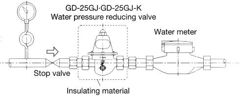
- Use the polystyrene package as insulation material.
- The belt of the packing box is the instruction manual. Please use it as a belt of heat insulating material after piping.
- There are two types of pipe end anti-corrosion core: the vinyl chloride lining steel pipe and the polyethylene powder lining steel pipe for water supply. Please use according to the pipe type since the inner diameter of steel pipe is different respectively.
DANGER
Pipe end anti-corrosion core has a risk of heat transformation by high temperature. Please avoid high temperature due to work near fire or welding work.
Piping construction procedure (pipe end anti-corrosion core):
- Check the pipe: Make sure that it is a suitable pipe type to the core. Please make sure to use the qualified pipe. Using out of qualification may lead to malfunction of the anticorrosive such as incomplete air-tightness, deformation of core, etc.
- Cutting the pipe: Please cut it off at a right angle to the axis. Please use an automatic metal sawing machine or circular sawing machine. Do not use high-speed grinding wheel cutting, pipe cutting, gas cutting, or arc cutting. Be sure to remove the oil adhering to the pipe.
- Chamfering of the pipe: Please lightly chamfer the burr of the inner surface of the tube by using a pipe chamfering tool such as a scraper.
- Threading of the pipe: Tap the screw according to JIS standard. Please check certainly at screw gauge because an out-of-standard screw will cause damage to the core.
- Application of the sealant: Please apply anti-corrosion sealant on the end and male thread.
- Joint of the pipe: Refer to the number of threads and length in the manual's reference table. It can be installed horizontally or vertically. Install after getting rid of foreign matter such as sand and scale inside the pipe.
How to Adjust the Pressure
- Screw the pressure gauge into the pressure gauge joint.
- Remove the cap. Checking the pressure gauge, turn the adjusting screw to adjust the reduced pressure to a desired level.
- The reduced pressure decreases when the adjusting screw is turned clockwise.
- The reduced pressure increases when the adjusting screw is turned counterclockwise.
- After reduced pressure adjustment, attach the cap.
- Remove the pressure gauge.
Piping Example