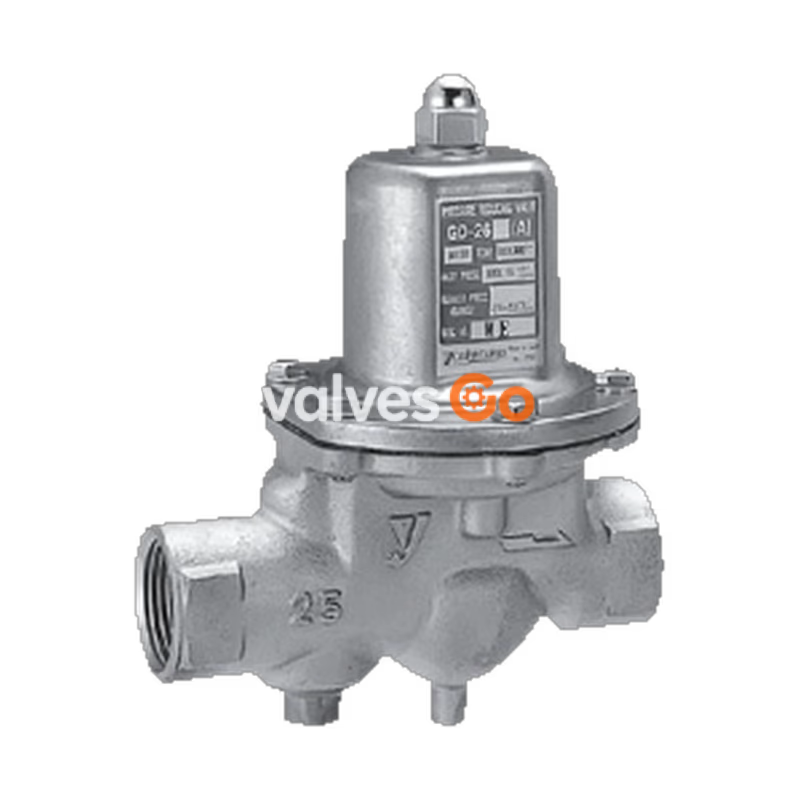
The Yoshitake GD-26G is a direct-acting pressure reducing valve designed for air and other non-dangerous fluids. It features a corrosion-resistant bronze body, EPDM valve disc and diaphragm, and a pressure balance structure that maintains a constant reduced pressure regardless of inlet pressure fluctuations. The valve is compact, lightweight, and allows for easy maintenance with top-access disassembly. A 40-mesh strainer is built into sizes 15A to 50A.
Related Models
The GD-27G is the flanged (JIS 10K FF) version of this valve. The GD-26GS and GD-27GS models feature stainless steel bodies and valve seats.
Features
- Corrosion-resistant materials are used for wetted parts.
- Reduced noise.
- Pressure balance structure can keep the reduced pressure at a constant level without being affected by inlet pressure.
- Maintenance and inspection can be conducted easily by disassembling simply from the upper side.
- Compact and lightweight, easy to handle on piping.
Specifications
| Model | GD-26G | GD-27G |
|---|
| Application | Air, Other non-dangerous fluids * | |
| Inlet pressure | 1.0 MPa or less | |
| Reduced pressure | (A) 0.05-0.35 MPa
(B) 0.3-0.7 MPa | |
| Fluid temperature | 5-90°C | |
| Minimum differential pressure | 0.05 MPa | |
| Maximum pressure reduction ratio | 10:1 | |
| Body Material | Bronze | |
| Valve seat Material | Bronze | |
| Valve disc Material | EPDM | |
| Diaphragm Material | EPDM | |
| Connection | JIS Rc screwed | JIS 10K FF flanged |
* Please contact us when using for gas containing oil.
Notes
- A strainer (40 mesh) is incorporated in 15A to 50A.
- 65A to 100A do not include strainer.
- Pressure gauge connection port is JIS Rc 1/8.
Dimensions and Weights
GD-26G
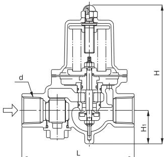
| Nominal size | d | L | H | $H_1$ | Weight (kg) |
|---|
| 15A | Rc 1/2 | 115 | 159.5 | 37.5 | 1.6 |
| 20A | Rc 3/4 | 120 | 159.5 | 38.5 | 1.7 |
| 25A | Rc 1 | 135 | 170 | 41 | 2.1 |
| 32A | Rc 1-1/4 | 180 | 224 | 57 | 4.0 |
| 40A | Rc 1-1/2 | 180 | 224 | 57 | 4.4 |
| 50A | Rc 2 | 200 | 239.5 | 61 | 6.5 |
Pressure Characteristic Chart
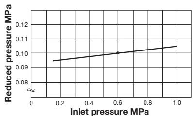
This chart shows variation in reduced pressure when the inlet pressure of 0.6 MPa is changed between 0.15 MPa and 1.0 MPa while the reduced pressure is set at 0.1 MPa.
Flow Characteristic Chart
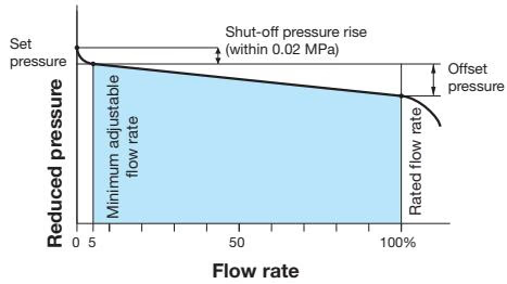
Offset
| Nominal size | Pressure range | Offset pressure |
|---|
| 15-100A | (A) 0.05-0.35 MPa | Within 0.05 MPa |
| 15-100A | (B) 0.3-0.7 MPa | Within 0.10 MPa |
Nominal Sizes Selection Chart
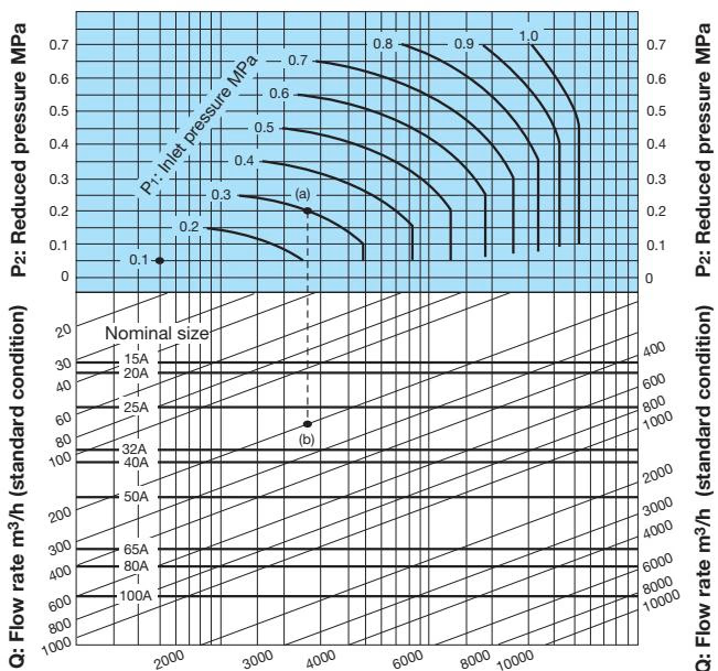
Example: When selecting the nominal size of a pressure reducing valve whose inlet pressure (P1), reduced pressure (P2), and flow rate are 0.3 MPa, 0.2 MPa, and 200 m³/h (standard condition), respectively, first find intersection point (a) of the inlet pressure (P1) of 0.3 MPa and the reduced pressure (P2) of 0.2 MPa. Trace down vertically from this intersection point to find intersection point (b) with the flow rate of 200 m³/h (standard condition). Since intersection point (b) lies between nominal sizes 25A and 32A, select the larger one, 32A.
* Set the safety factor at 80 to 90%.
Installation
Piping Example
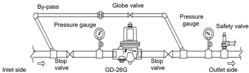
The product can be installed either horizontally or vertically.
Precaution for Installation
Warning
- When installing a safety relief valve for equipment protection at the outlet side of the product, connect a blow-off pipe to the outlet side of the safety relief valve, and lead it to a place where there is no risk of physical damage even if fluid blows out. Failure to follow this notice may result in injury and scalds in the event that high temperature fluid blows out.
Caution
- Do not disassemble the product unless it is necessary. Unnecessary disassembly prevents the product from functioning properly.
- Before installing the product in the piping, be sure to remove foreign substances and scale from the piping. Ingress of foreign substances, scale or seal agent into the product leads to valve leakage or malfunction of the product.
- If components having negative influence on internal parts are included in fluid or surroundings, deterioration of rubber parts is accelerated and then outside leakage or functional disorder is caused.
- Be sure to install a strainer at the inlet side of the product of nominal size 65A to 100A. Ingress of foreign substances or scale into the product leads to malfunction of the product. It is recommended to use a strainer of 40 mesh or more.
- Install a safety relief valve for equipment protection at the outlet side of the product. Failure to follow this notice may result in damage of the equipment.
- Be sure to install pressure gauges at the inlet and outlet sides of the product. Failure to follow this notice hampers correct pressure adjustment.
- If a quick operating valve such as a solenoid valve is installed, place it at a distance of at least 3 meters from the product. Failure to follow this notice may result in malfunction or a drastically shortened service life of the product.
- For two-stage pressure reduction, keep a distance of at least 3 meters between each product. Failure to follow this notice may prevent the product from functioning properly due to malfunction.
- Install the product properly by checking the inlet, outlet and proper posture. Installing the product in wrong directions prevents the product from functioning properly.
- Install pipes so that excessive load, torque or vibration is not applied to the product. Failure to make durability lower or cause malfunction.
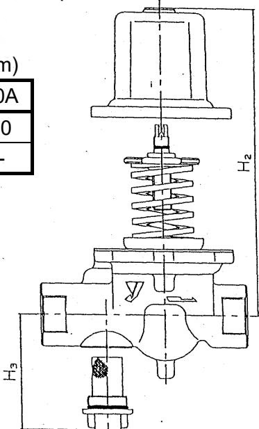
| Nominal size | 15A | 20A | 25A | 32A | 40A | 50A | 65A | 80A | 100A |
|---|
| $H_2$ | 240 | 250 | 250 | 300 | 300 | 320 | 450 | 450 | 550 |
| $H_3$ | 80 | 90 | 90 | 120 | 120 | 150 | --- | --- | --- |
Operation Procedure
Precaution for Operation
Warning
- When the product is used for hot fluid, do not touch the product with bare hands. The product having hot fluid may scald your skin.
- Before leading fluid, make sure that there is no danger even if fluid leads to the piping end.
Caution
- Before leading fluid into the product, close the stop valves at the inlet and outlet of the product and remove foreign substances and scale from the piping completely by using a bypass line. Failure to follow this notice may prevent the product from functioning properly due to the ingress of foreign substances and scale into the product.
- To adjust the set pressure, turn the adjusting screw slowly. Failure to follow this notice may result in damage to the product and other equipment due to hunting or other cause.
- When adjusting the pressure, be sure to keep the shut-off valve on the outlet-side piping slightly open. Failure to follow this notice may result in damage to the product due to adjustment beyond the allowable adjustment range while a large flow rate is passing through the valve (for example, when the shut-off valve on the outlet-side piping is fully open).
- When the product is not used for an extended period, completely discharge fluid from the product and pipes, and close the stop valves at the inlet and outlet sides of the product. Failure to follow this notice causes malfunction of the product due to rusting inside the product and the pipes.
Adjusting Procedure
Following a wrong adjusting procedure may cause hunting, scale problems or other problem, and can heavily damage the main parts of the valve. To avoid these problems, be sure to follow the procedure given below.
- Close the stop valves at the inlet and outlet sides of the reducing valve, and take adequate time to blow out fluid by using a bypass line. In doing this, adjust the opening of the globe valve in the bypass pipe so as not to blow out the safety relief valve. After the end of blowing, close the globe valve without fail.
- Fully open the stop valve at the inlet side slowly, and open the stop valve at the outlet side so that a little fluid can flow through.
- Remove the domed cap nut [17] and turn the adjusting screw [14] while watching the pressure gauge at the outlet side.
- Turn the adjusting screw to the right (clockwise) to increase the reduced pressure.
- Turn the adjusting screw to the left (counterclockwise) to decrease the reduced pressure. * If the outlet pressure does not change when the adjusting screw is turned, discontinue the pressure adjustment and follow the instructions in Section 5.1, "Troubleshooting."
- Fully open the stop valve at the outlet side slowly.
- After the adjustment is complete, tighten the domed cap nut [17].
Maintenance
Troubleshooting
| Trouble | Cause | Remedy |
|---|
| Reduced pressure does not reach the desired value. | 1. The working pressure is improper.
2. The nominal size of the product is too small for the flow rate for use.
3. Pressure adjustment is improper.
4. Strainer built in the product is clogged.
5. Pressure gauge is broken. | 1. Correct the working pressure.
2. Replace the product with the proper nominal size.
3. Readjust the pressure in accordance with the given procedure.
4. Clean the strainer.
5. Replace pressure gauge. |
| Abnormal pressure rises at the outlet side. | 1. Foreign substances stuck between the disc [8] and the valve seat [3], or scratch on them.
2. The O-ring [6] is damaged.
3. The diaphragm [9] is damaged.
4. There is a leakage from the globe valve of the by-pass line. | 1. Disassemble the product and remove the foreign substances. If scratch is observed on the valve disc or valve seat, replace it.
2. Replace the O-ring.
3. Replace the diaphragm.
4. Repair or replace the globe valve. |
| Abnormal sound | 1. The nominal size of the product is too large for the specifications of the system.
2. The pressure reduction ratio is too large or the maximum pressure difference is exceeded.
3. A quick operating valve is located near the product. | 1. Replace the product with the proper nominal size.
2. Reduce pressure in two stages.
3. Keep a distance between them as large as possible. |
INFO
- Most of problems with the pressure reducing valve are caused by foreign substances and scale in the piping. Avoid the ingress of dust and dirt to the product with caution.
- A phenomenon similar to valve failure could occur due to the failure of the pressure gauge, leakage or insufficient tightening of the globe valve in the by-pass line, clogging of the strainer, and other causes. Check the above possible causes and take a proper remedy and preventive measures.
Precaution for Disassembly and Inspection
Warning
- Completely discharge the pressure inside of the product, piping and equipment before disassembly and inspection. Disassembly and inspection must be done by experienced professional or valve manufacturer. Failure to follow this notice may result in scalds, injury or contamination on the surroundings due to the residual pressure.
- When the product is used for hot fluid, do not touch the product with bare hands. The product having hot fluid may scald your skin.
Caution
- If problem occurs for a cause other than listed in "Troubleshooting", please contact us.
- When the product is disassembled, internal fluid flows out. Receive it in a container. Failure to follow this notice may result in making the surroundings dirty.
- Use appropriate tools for disassembly and assembly. Failure to follow this notice may result in damage to the components.
- Synthetic rubber is a consumable part. The replacement interval of the synthetic rubber part greatly varies depending on the use conditions. The general guide for the replacement interval is shown below.
| Recommended replacement year | Part name |
|---|
| Three years | Diaphragm [9], O-ring [6], Disc [8] |
| Five years | O-ring [20], [24], [26], [28], [30], [45] |
Exploded View
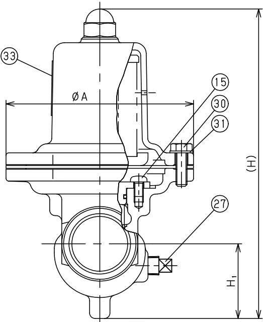
| No. | Name of Parts | Material | Q.TY |
|---|
| 1 | Body | Bronze | 1 |
| 2 | Spring Chamber | Aluminium | 1 |
| 3 | Valve Seat | Bronze | 1 |
| 4 | O Ring | NBR | 1 |
| 5 | O Ring | NBR | 1 |
| 6 | Spindle | Stainless Steel | 1 |
| 7 | Retainer | Bronze | 1 |
| 8 | O Ring | NBR | 1 |
| 9 | O Ring | NBR | 1 |
| 10 | Disc Cover | Bronze | 1 |
| 11 | O Ring | NBR | 0 or 1 |
| 12 | Disc | EPDM | 1 |
| 13 | Washer of Disc | Bronze | 0 or 1 |
| 14 | U Nut | Stainless Steel | 1 |
| 15 | Screw or Bolts | Stainless Steel | 2 |
| 17 | Diaphragm | EPDM | 1 |
| 18 | Strainer | Stainless Steel | 1 |
| 19 | Strainer Cap | Bronze | 1 |
| 20 | O Ring | NBR | 1 |
| 21 | Diaphragm Shell | Brass | 1 |
| 22 | Spring Plate | Brass | 1 |
| 23 | Adjusting Screw | Stainless Steel | 1 |
| 24 | Packing | Copper | 1 |
| 25 | O Ring | NBR | 1 |
| 26 | Spring | Alloy Steel | 1 |
| 27 | Plug | Stainless Steel or Cast Stainless Steel | 1 |
| 28 | Nut | Stainless Steel | 1 |
| 29 | Spring Washer | Stainless Steel | 1 |
| 30 | Bolt | Stainless Steel | 6 |
| 31 | Washer | Stainless Steel | 6 |
| 32 | Domed Cap Nut | Rolled Steel | 1 |
| 33 | Label | Polyester | 1 |