


PN25

Yoshitake GD-26S series direct type pressure reducing valve. Features a cast stainless steel body for cold and hot water applications, low noise, and a built-in strainer.
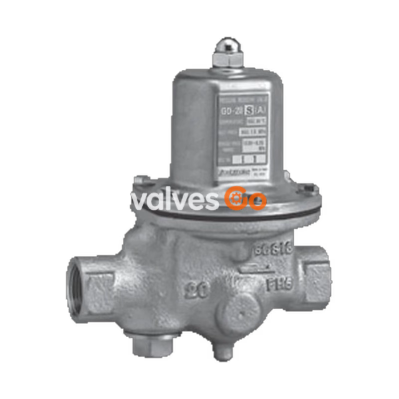
Yoshitake GD-26S series pressure reducing valves are designed for cold and hot water applications. The wetted parts are made of cast stainless steel (corrosion-resistant material) to prevent rusty water, making them suitable for environments where clean water is essential. The series includes the GD-26S, GD-26S-NE, GD-27S, GD-27S-NE, GD-28S, GD-29S, and GD-29S-NE models.

| Model | GD-26S, GD-26S-NE, GD-27S, GD-27S-NE | GD-28S, GD-29S, GD-28S-NE, GD-29S-NE |
|---|---|---|
| Application | Cold and hot water | Cold and hot water |
| Inlet pressure | 1.0 MPa or less | 1.6 MPa or less (2.0 MPa or less for some variants) |
| Reduced pressure | (A) 0.05-0.35 MPa (B) 0.3-0.7 MPa | (A) 0.2-0.35 MPa (GD-28S) (B) 0.3-0.7 MPa |
| Minimum differential pressure | 0.05 MPa | 0.05 MPa |
| Maximum pressure reduction ratio | 10:1 | 7:1 (for GD-28S/29S) |
| Application temperature | 5-90℃ | 5-90℃ |
| Body / Valve seat material | Cast stainless steel | Cast stainless steel |
| Valve disc / Diaphragm | EPDM or FKM / EPDM | EPDM |
| Connection | JIS Rc screwed / JIS 10K FF flanged | JIS Rc screwed / JIS 16K/20K FF flanged |
INFO
| Nominal size | d | L | H | H1 | Weight (kg) |
|---|---|---|---|---|---|
| 20A | Rc 3/4 | 135 | 170 | 41 | 2.2 (2.3) |
| 25A | Rc 1 | 135 | 170 | 41 | 2.2 (2.3) |
| 32A | Rc 1-1/4 | 180 | 224 | 57 | 4.7 (4.9) |
| 40A | Rc 1-1/2 | 180 | 224 | 57 | 4.5 (4.7) |
| 50A | Rc 2 | 200 | 239.5 | 61 | 6.5 (6.7) |
The values in parentheses are for GD-28S-NE.
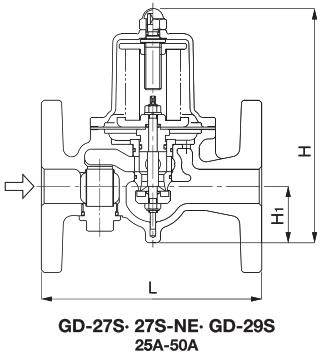
| Nominal size | L | H | H1 | Weight (kg) |
|---|---|---|---|---|
| 20A | 160 | 170 | 41 | 3.9 |
| 25A | 160 | 170 | 41 | 4.8 |
| 32A | 200 | 224 | 57 | 8.0 |
| 40A | 200 | 224 | 57 | 8.3 |
| 50A | 220 | 239.5 | 61 | 10.8 |
| 65A | 220 | 329 | 77 | 20.6 |
| 80A | 230 (234) | 345 | 82 | 22.0 (25.0) |
| 100A | 270 (278) | 412 | 94 | 34.5 (36.5) |
The values in parentheses are the dimensions and weights of the GD-29S.
If the differential pressure before and after the valve is 0.15 MPa or more:
| Nominal size | 15A | 20A | 25A | 32A | 40A | 50A | 65A | 80A | 100A | 125A | 150A |
|---|---|---|---|---|---|---|---|---|---|---|---|
| Rated flow (L/min) | 30 | 40 | 60 | 100 | 150 | 250 | 300 | 450 | 700 | 1,600 | 1,800 |
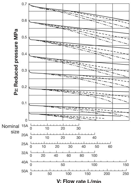
If the differential pressure is less than 0.15 MPa, select the nominal size from the flow rate charts.
Nominal size: 15A to 50A
Nominal size: 65A to 100A
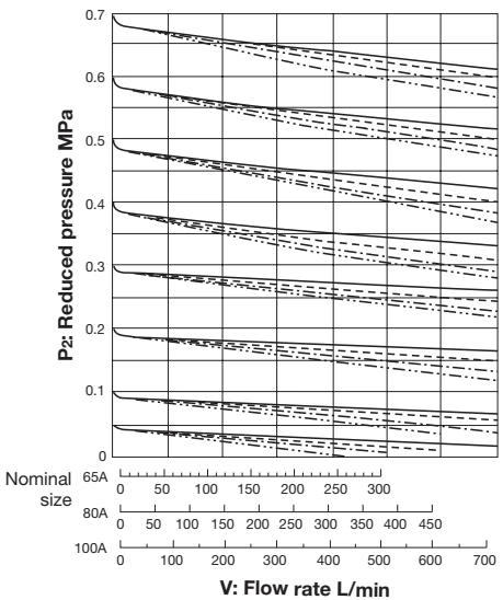
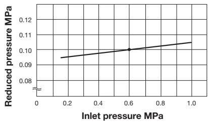
This chart shows variation in reduced pressure when the inlet pressure of 0.6 MPa is changed between 0.15 MPa and 1.0 MPa while the reduced pressure is set at 0.1 MPa.
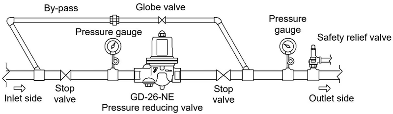
TIP
WARNING
Before installing the product in the piping, be sure to remove foreign substances and scale from the piping completely. Ingress of foreign substances or scale into the product leads to valve leakage or malfunction.
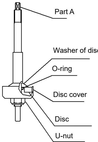
DANGER
Completely discharge the pressure inside of the product, piping, and equipment before disassembly and inspection. Failure to follow this notice may result in scalds or injury due to the residual pressure.
Clean the strainer regularly at least once or twice a year to prevent flow rate decrease and product malfunction.
Yoshitake Control Valves / Pressure Reducing Valves
GP, GD, and CP series for stable pressure reduction and control in steam, water, and air systems.
Explore similar products in our catalog



