


PN25

Yoshitake GD-29-NE pressure reducing valve for cold and hot water. Features 1.6 MPa max inlet pressure, JIS 16K FF flanged connection, and cast bronze body.
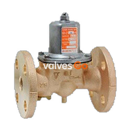
Yoshitake GD-29-NE is a pressure reducing valve designed for cold and hot water applications. It operates with an inlet pressure of up to 1.6 MPa and features a cast bronze body with a pressure balance structure to keep reduced pressure constant.
| Specification | Value |
|---|---|
| Nominal Size | 25A-100A |
| Application | Cold and hot water |
| Inlet Pressure | 1.6 MPa or less |
| Reduced Pressure | (A) 0.05-0.35 MPa (B) 0.30-0.70 MPa |
| Minimum Differential Pressure | 0.05 MPa |
| Maximum Pressure Reduction Ratio | 10:1 |
| Maximum Temperature | 90°C |
| Body | Cast bronze (NPb-treated) |
| Valve Seat | Cast bronze (NPb-treated) |
| Valve Disc | FKM |
| Diaphragm | EPDM |
| Connection | JIS 16K FF flanged |
INFO
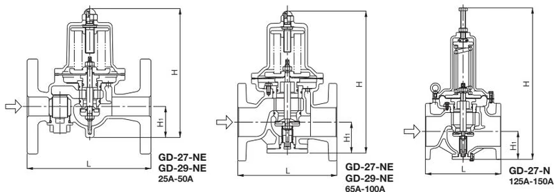
| Nominal Size | L | H | H1 | Weight (kg) |
|---|---|---|---|---|
| 25A | 160 | 170 | 41 | 5.1 |
| 32A | 200 | 224 | 57 | 7.5 |
| 40A | 200 | 224 | 57 | 7.7 |
| 50A | 220 | 239.5 | 61 | 10.9 |
| 65A | 220 | 329 | 77 | 20.0 |
| 80A | 234 | 345 | 82 | 24.0 |
| 100A | 278 | 412 | 94 | 36.5 |
Note: Values specific to the 80A and 100A GD-29-NE are extracted from the source dimensions table parentheses.
(1) The differential pressure before and after the valve is 0.15 MPa or more.
| Nominal Size | 25A | 32A | 40A | 50A | 65A | 80A | 100A |
|---|---|---|---|---|---|---|---|
| Rated flow rate (L/min) | 60 | 100 | 150 | 250 | 300 | 450 | 700 |
(2) If the differential pressure before and after the valve is less than 0.15 MPa, select a proper nominal size from the appropriate chart shown below.
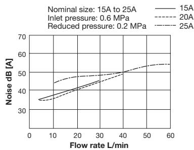
Nominal size: 15A to 50A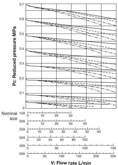
Nominal size: 65A to 100A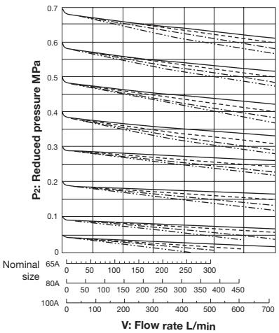
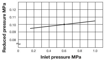 This chart shows variation in reduced pressure when the inlet pressure of 0.6 MPa is changed between 0.15 MPa and 1.0 MPa while the reduced pressure is set at 0.1 MPa.
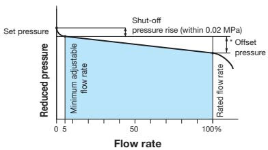
Offset Pressure
| Nominal Size | Pressure Range | Reduced Pressure Range | Offset Pressure |
|---|---|---|---|
| 25A-100A | A | 0.05-0.35 MPa | Within 0.05 MPa |
| 25A-100A | B | 0.30-0.70 MPa | Within 0.10 MPa |
WARNING
Precaution for installation
Yoshitake Control Valves / Pressure Reducing Valves
GP, GD, and CP series for stable pressure reduction and control in steam, water, and air systems.
Explore similar products in our catalog



