


PN25

Yoshitake GP-1000H and GP-1000HEN pilot-operated piston pressure reducing valves for steam. Features 0.1-1.6 MPa inlet pressure, 20:1 reduction ratio, and ductile cast iron body.
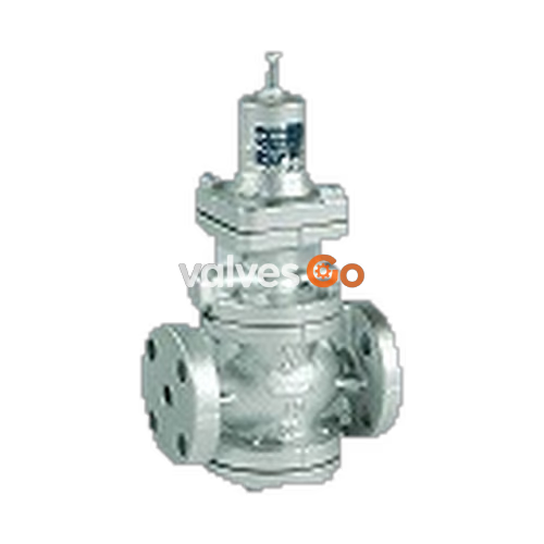
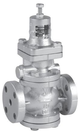
The Yoshitake GP-1000H and GP-1000HEN are pilot-operated, piston-type pressure reducing valves designed specifically for steam applications. They respond sharply to fluctuations in inlet pressure and changes in flow rate, ensuring the reduced pressure is maintained at a constant level. The GP-1000HEN model complies with the face-to-face dimensions of the EN standard (except for 15A), making it an easy replacement for existing valves. Both models offer a wide set pressure range and are compliant with the SHASE-S106 standard for pressure reducing valves.
| Specification | GP-1000HEN | GP-1000H |
|---|---|---|
| Application | Steam | Steam |
| Inlet pressure | 0.1-1.6 MPa | 0.1-1.6 MPa |
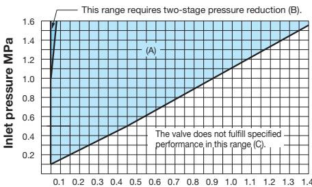
| Reduced pressure | (A) 0.05-0.9 MPa (B) 0.9-1.4 MPa | (A) 0.05-0.9 MPa (B) 0.9-1.4 MPa |
| Minimum differential pressure | 0.05 MPa | 0.05 MPa |
| Maximum pressure reduction ratio | 20:1 | 20:1 |
| Maximum temperature | 220°C | 220°C |
| Valve seat leakage | 0.01% or less of rated flow rate | 0.01% or less of rated flow rate |
| Body Material | Ductile cast iron | Ductile cast iron |
| Main valve, valve seat | Stainless steel | Stainless steel |
| Pilot valve, pilot valve seat | Stainless steel | Stainless steel |
| Piston, cylinder | Stainless steel | Stainless steel |
| Diaphragm | Stainless steel | Stainless steel |
| Connection | EN PN25 flanged | JIS 16K FF flanged ASME Class 300 flanged |
Note: For 15A, 20A, ASME flange is not available.
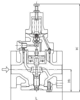
| Nominal size | L (GP-1000HEN) | L (GP-1000H) | H | H1 | Weight (GP-1000HEN) | Weight (GP-1000H) |
|---|---|---|---|---|---|---|
| 15A | 150 | 150 (-) | 291 | 64 | 8.0 kg | 8.0 (-) kg |
| 20A | 150 | 155 (-) | 291 | 64 | 8.5 kg | 8.5 (-) kg |
| 25A | 160 | 160 (160) | 300 | 67 | 10.0 kg | 10.0 (10.0) kg |
| 32A | 180 | 190 (180) | 333 | 82 | 14.0 kg | 14.0 (14.0) kg |
| 40A | 200 | 190 (200) | 333 | 82 | 15.5 kg | 14.5 (15.5) kg |
| 50A | 230 | 220 (230) | 353 | 93 | 21.0 kg | 20.0 (21.0) kg |
| 65A | 290 | 245 (278) | 357 | 100 | 30.0 kg | 30.0 (30.0) kg |
| 80A | 310 | 290 (310) | 404 | 122 | 37.0 kg | 35.0 (37.0) kg |
| 100A | 350 | 330 (350) | 450 | 144 | 57.0 kg | 52.5 (57.0) kg |
Note: The values in parentheses are the dimensions of ASME Class 300 flanged.
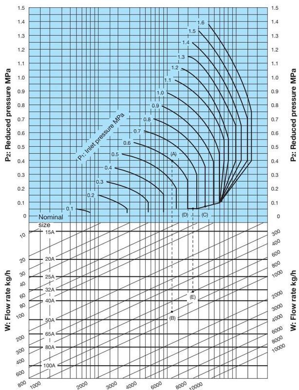
Find the intersection point of the inlet and reduced pressures. If the intersection point is within range (A) in the chart, the pressures are controllable with a single pressure reducing valve. They can be controlled by two-stage pressure reduction if the intersection point is within range (B). The valve does not fulfill specified performance in range (C).
| Reduced pressures (MPa) | Safety valve setting pressure (MPa) |
|---|---|
| 0.03~0.1 | Reduced pressures + more than 0.05 |
| 0.1~0.4 | Reduced pressures + more than 0.08 |
| 0.4~0.6 | Reduced pressures + more than 0.1 |
| 0.6~0.8 | Reduced pressures + more than 0.12 |
| 0.8~1.4 | Reduced pressures + 15% |
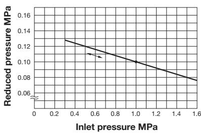
This chart shows variation in reduced pressure when the inlet pressure of 1.0 MPa is changed between 0.3 MPa and 1.6 MPa while the reduced pressure is set at 0.1 MPa.
| Nominal size | 15A | 20A | 25A | 32A | 40A | 50A | 65A | 80A | 100A |
|---|---|---|---|---|---|---|---|---|---|
| Rated Cv values | 1 | 2.3 | 4 | 6.5 | 9 | 16 | 25 | 36 | 64 |
Note on Cv Correction
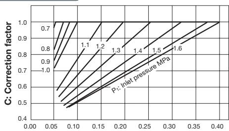
When the reduced pressure is within either of the ranges shown below, calculate the corrected Cv value by multiplying the rated Cv value by the correction factor C obtained from the chart below.
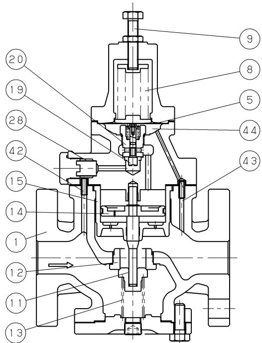
The pressure-reducing valve reduces pressure by throttling the valve. The valve is composed of the main valve and main valve seat for throttling, and adjusting spring, diaphragm, pilot valve, and piston for pressure sensing and activation.
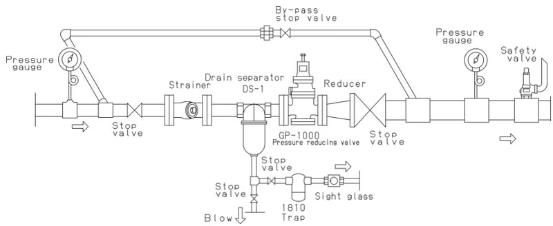
Precautions during installation
Provide space on the top and bottom of the valve so that the valve can be easily disassembled and inspected.
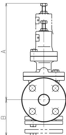
| Nominal size | A (mm) | B (mm) |
|---|---|---|
| 15A, 20A, 25A | 315 | 125 (15A, 20A) / 135 (25A) |
| 32A, 40A | 335 | 155 |
| 50A | 345 | 175 |
| 65A | 355 | 190 |
| 80A | 375 | 225 |
| 100A | 395 | 265 |
| Problem | Cause | Solution |
|---|---|---|
| Pressure does not reach the desired value. | Incorrect pressure is being used. Strainer is clogged. Foreign matter exists between piston and cylinder. Piston ring is damaged. Nominal size is too small for the specifications. Pressure is not adjusted correctly. Strainer installed before pressure reducing valve is clogged. Pressure gauge is faulty. | Correct the pressure. Disassemble and clean the strainer. Disassemble and remove the foreign matter. Polish scratches away using paper. Change parts if scratches still exist. Replace the piston ring. Change the nominal size appropriately. Observe the adjustment procedures and readjust pressure. Disassemble and clean it. Replace it. |
| Reduced pressure raises above than the specified value. | Foreign matter exists between main valve and main valve seat, or scratches exist. Foreign matter exists between pilot valve and pilot valve seat, or scratches exist. Foreign matter exists between piston and cylinder. Trap is not provided for dead-end line. By-pass valve is leaking. Diaphragm is damaged. | Disassemble and remove the foreign matter. Lap the main valve and main valve seat if scratched. Change parts if scratches still exist. Disassemble the pilot valve assembly, and clean or replace it. Disassemble and remove the foreign matter. Polish scratches away using paper. Install a trap. Repair or replace it. Replace the diaphragm. |
| Abnormal noise is heard. | Nominal size is too large for the specifications. Pressure reducing ratio is too large. Drainage problem is caused. An abrupt OPEN/CLOSE valve is located too close to the pressure reducing valve. Outlet pipe is too small. | Change the nominal size appropriately. Reduce pressure in two stages. Install a trap. Allow as much space as possible between the valves. Select a pipe size that will produce a flow velocity of 30m/s or less. |
Warning
Be sure that the stop valves at the inlet and outlet side of the pressure reducing valve are closed and all internal pressure and condensate have discharged before disassembling the valve. While disassembly, drain flow out from the valve, so catch it by container.
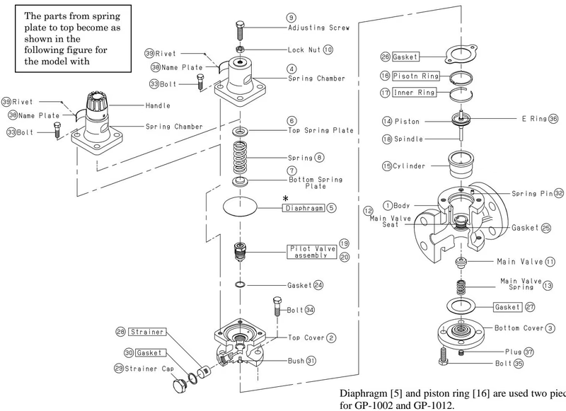
| No. | Name of parts | Replace period |
|---|---|---|
| 5 | Diaphragm | 2 years |
| 16 | Piston ring | 3 years |
| 17 | Inner ring | 3 years |
| 19, 20 | Pilot valve assembly | 5 years |
| 24 | Gasket | 5 years |
| 26, 27 | Gasket | 2 years |
| 28 | Strainer | 5 years |
| 30 | Gasket | 2 years |
Yoshitake Control Valves / Pressure Reducing Valves
GP, GD, and CP series for stable pressure reduction and control in steam, water, and air systems.
Explore similar products in our catalog



