3450 RPM Motors

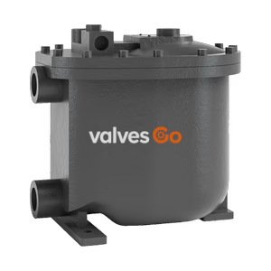
Yoshitake PF-2000 ultra-compact pumping trap for steam condensate. Driven by steam or air (0.03-0.5 MPa), no electricity required. Ductile cast iron body.
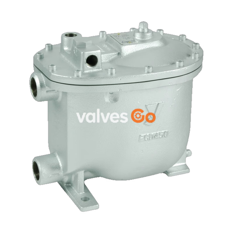
Yoshitake PF-2000 Pumping Trap is an ultra-compact mechanical pump designed for the efficient recovery and discharge of steam condensate and non-hazardous fluids. Operating on either steam or air pressure, it requires no electrical equipment, making it suitable for a wide range of industrial environments, including tight spaces and hazardous areas.
The PF-2000 features a durable ductile cast iron (FCD450) body and stainless steel trim parts. Its design allows for easy maintenance, as the main internal components are attached to the cover, enabling inspection and repair without removing the body from the piping.
| Specification | Value |
|---|---|
| Nominal size | 25A |
| Application | Steam condensate, Non-hazardous fluid |
| Motive fluid | Steam / Air |
| Max. working pressure | 0.5 MPa |
| Motive pressure | 0.03 to 0.5 MPa *1 |
| Motive differential pressure | (Back pressure + 0.03 MPa) to 0.5 MPa |
| Max. working temperature | 160°C |
| Body Material | Ductile cast iron (FCD450) |
| Trim parts / Float (P) | Stainless steel |
| Connection | JIS Rc screwed |
| Check valve at inlet side | Built-in (swing type) |
| Check valve at outlet side | Externally attached *2 |
*1 The most appropriate value of motive pressure is back pressure at outlet side + 0.1 to 0.2 MPa. *2 Install an optional check valve (SCV-2 or SCV-3) at the inlet and outlet side of the product.
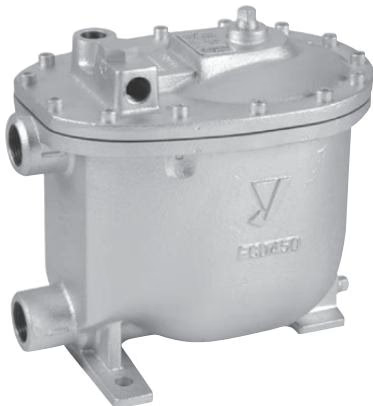
Connection Diameters:
| Condensate inlet | Condensate outlet | Motive pressure port | Vent port |
|---|---|---|---|
| Rc 1 | Rc 1 | Rc 1/2 | Rc 1/2 |
Weight: 17 kg
The flow rate described below indicates condensate volume when the condensate flow-in height is 800 mm above the bottom of the product.
| Motive Pressure [MPa] | Back pressure [MPa] | Steam motive (kg/h) | Air motive (kg/h) |
|---|---|---|---|
| 0.1 | 0.05 | 364 | 671 |
| 0.2 | 0.05 | 508 | 763 |
| 0.3 | 0.05 | 606 | 781 |
| 0.4 | 0.05 | 664 | 795 |
| 0.5 | 0.05 | 666 | 800 |
| 0.2 | 0.1 | 309 | 725 |
| 0.3 | 0.1 | 454 | 756 |
| 0.4 | 0.1 | 508 | 764 |
| 0.5 | 0.1 | 513 | 769 |
| 0.3 | 0.2 | 282 | 699 |
| 0.4 | 0.2 | 315 | 724 |
| 0.5 | 0.2 | 319 | 730 |
| 0.4 | 0.3 | 243 | 656 |
| 0.5 | 0.3 | 292 | 695 |
| 0.5 | 0.4 | 208 | 643 |
Discharge capacity varies depending on condensate flow-in-height. Multiply the volume by the following factors according to the condensate flow-in-height (the height from the bottom of the product to the bottom part of the receiver).
| Motive fluid | 600 mm | 800 mm | 1000 mm | 1200 mm | 1400 mm |
|---|---|---|---|---|---|
| Steam | 0.90 | 1.0 | 1.05 | 1.10 | 1.15 |
| Air | 0.85 | 1.0 | 1.15 | 1.25 | 1.35 |
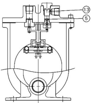
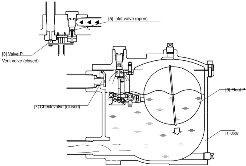
State 1 (Filling): Condensate flows into the body via the condensate inlet and check valve, and the float (P) moves upward due to buoyancy.
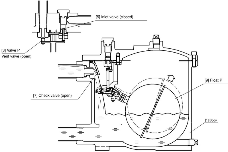
State 2 (Discharging): When the condensate level rises and the float (P) reaches a certain height, the inlet valve is opened by valve (P), and then the vent valve of valve (P) closes. The driving pressure enters the body following the opening of the inlet valve, closing the check valve and stopping the condensate flowing in. Condensate inside the body is transferred to the outlet side and discharged. When condensate is discharged, the float (P) moves downward in line with the water level in the body. When it drops to a certain height, the inlet valve is closed and the vent valve of valve (P) opens. Internal pressure is released by the vent valve, returning to State 1.
Installation Cautions
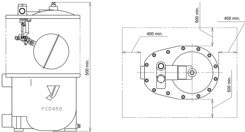
Maintenance Space
Be sure to secure the maintenance space needed for disassembly and repair of the product as shown in the diagram above (dimensions in mm).
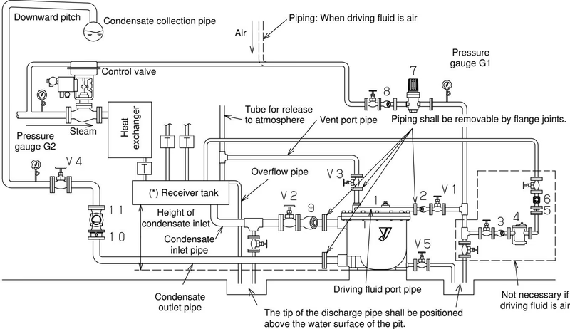
A receiver tank is used for the separation of flash steam and condensate, condensate temporary storage, and protection of the pumping trap. Be sure to install a receiver tank before using the pumping trap.
Most failures of the product are caused by foreign materials in the pipes. Be especially careful to flush pipes before installation.
Maintenance Safety
Be sure to release internal pressure of the product, pipes, and devices completely and cool down the product before disassembly and inspection. Do not touch the product with bare hands until it is cooled down completely.
The following parts should be replaced at recommended intervals to maintain functions and performance:
| Trouble | Cause | Remedy |
|---|---|---|
| Condensate is not discharged. | Stop valve at condensate inlet is closed. | Open stop valve. |
| Pipes at condensate inlet and outlet are connected the other way around. | Connect the pipes correctly. | |
| Strainer at condensate inlet is clogged. | Disassemble strainer and clean the screen. | |
| Driving pressure is too low to resist back pressure. | Control the pressure to a specified level by adjusting the reducing valve. | |
| Check valve at condensate outlet is installed in opposite direction or does not open. | Install in proper direction or replace. | |
| Leakage from vent valve at valve (P). | Disassemble and clean scales, or replace valve (P) if scratched. | |
| Float (P) is broken. | Disassemble the product and replace Float (P). | |
| Leakage of steam to external area. | Leakage from gasket between body and cover. | Replace gasket. |
| Leakage from strainer gasket. | Replace strainer gasket. |
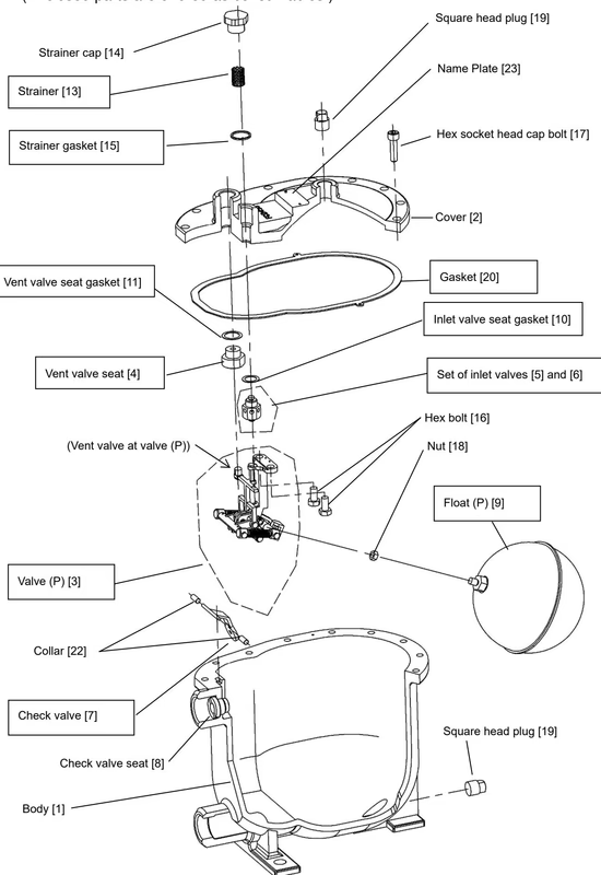
Disassembly Method:
Assembly Method:
Yoshitake Pumps / Automatic Pump Traps
PF-7000 and TFA-2000 automatic pump trap series for condensate recovery under high back pressure.
Explore similar products in our catalog