Ductile Cast Iron
Yoshitake SY-20-20 Y-type strainer for steam, air, water, and oil. Features a cast carbon steel body, stainless steel 80 mesh screen, and JIS 20K flanged connection rated up to 2.0 MPa and 260°C.
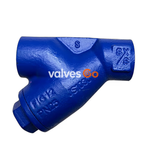
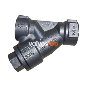
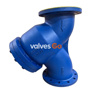
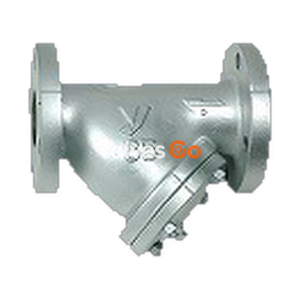
Yoshitake SY-20-20 is a high-flow-rate marine type Y-strainer designed for removing dust, scale, and other foreign matter from water, oil, steam, air, and other non-dangerous fluids. It is mainly used for cooling water and industrial water applications. It features a cast carbon steel body with a JIS 20K RF flanged connection and a stainless steel screen with 80 mesh as standard. The design provides the largest possible filtration area to minimize flow rate decreases caused by clogging.
| Specification | Value |
|---|---|
| Application | Steam, Air, Cold and hot water, Oil, Other non-dangerous fluids |
| Nominal Size | 15A - 250A |
| Maximum Pressure | 2.0 MPa |
| Maximum Temperature | 260℃ (If the temperature is over 260°C, please contact the manufacturer) |
| Body Material | Cast carbon steel (SCPH2) |
| Screen Material | Stainless steel (SUS304) |
| Screen Perforation | φ6-8P (φ6-1.80 holes/cm²) |
| Screen Mesh | Standard 80 mesh (20 to 60 mesh also available) |
| Connection | JIS 20K RF flanged |
Related Models
The source documentation also covers related models such as SY-20-10 (JIS 10K RF flanged, 1.0 MPa), SY-10-30 (JIS 30K RF flanged, 3.0 MPa), and high-pressure gas approved variants (SY-10H, SY-10HS series). The dimensions and specifications in this page focus on the SY-20-20 model.
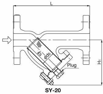
| Nominal Size | L (mm) | H1 (mm) | Screen ds (mm) | Screen ls (mm) | d (mm) | Plug | Weight (kg) |
|---|---|---|---|---|---|---|---|
| 15A | 160 | 104 | 25 | 56.5 | 15 | R3/8 | 3.2 |
| 20A | 160 | 113 | 30 | 67.5 | 20 | R3/8 | 4.0 |
| 25A | 180 | 122 | 33 | 75.0 | 25 | R3/8 | 5.9 |
| 32A | 240 | 154 | 55 | 101.0 | 40 | R1/2 | 9.3 |
| 40A | 240 | 154 | 55 | 101.0 | 40 | R1/2 | 9.3 |
| 50A | 260 | 174 | 57 | 114.5 | 50 | R1/2 | 13.0 |
| 65A | 275 | 187 | 74 | 124.0 | 65 | R1/2 | 15.8 |
| 80A | 360 | 241 | 90 | 167.0 | 80 | R3/4 | 28.0 |
| 100A | 362 | 280 | 114 | 187.0 | 100 | R3/4 | 37.8 |
| 125A | 415 | 330 | 140 | 224.5 | 125 | R3/4 | 57.0 |
| 150A | 520 | 386 | 184 | 308.5 | 150 | R3/4 | 82.8 |
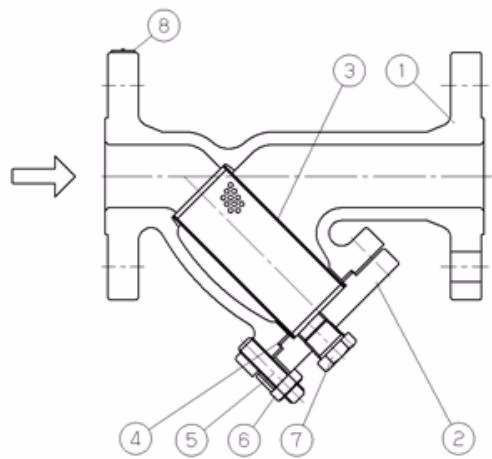
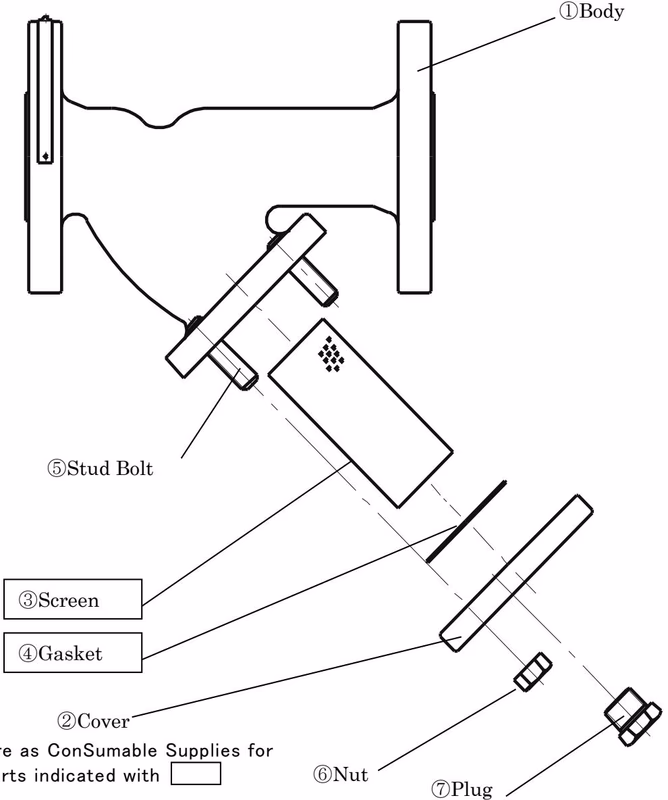
| No. | Name of Parts | Material |
|---|---|---|
| 1 | Body | Cast Steel (SCPH2) |
| 2 | Cover | Cast Steel (SCPH2) |
| 3 | Screen | Stainless Steel (SUS304) |
| 4 | Gasket | Non-Asbestos |
| 5 | Stud Bolt | Alloy Steel (SNB7) |
| 6 | Nut | Alloy Steel (SNB7) |
| 7 | Plug | Carbon Steel (SF490A) |
| 8 | Name Plate | Stainless Steel (SUS304) |
The screen (3) removes dust, scale, and other foreign matter out of the fluid flowing from the inlet port of the strainer.
To use the strainer most effectively, ensure the piping size matches the strainer size. Selecting a smaller strainer size will increase pressure drop and the required equipment entrance pressure might not be maintained.
Standard Flow Velocity (Reference JIS F7101):
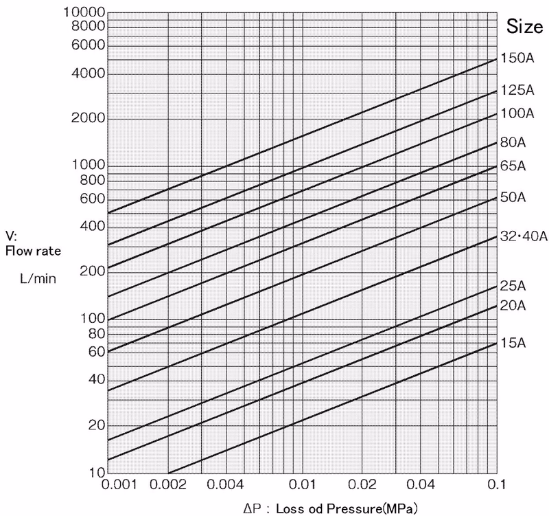 (Screen: Perforated plate φ6.0-1.80 holes/cm², Element 80 mesh)
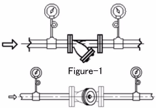
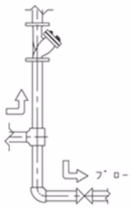
Installation Recommendations
Installation Warnings
Operation Warnings
| Trouble condition | Cause of trouble | Countermeasure and remedy |
|---|---|---|
| No fluid flows. | 1. Screen is clogged up. 2. Stop valves at inlet and/or outlet side are shut. | 1. Disassemble and clean the screen. 2. Open stop valves. |
| Pressure loss is excessive. | 1. Screen is clogged up. 2. Pressure gauge is damaged. | 1. Disassemble and clean the screen. 2. Renew the pressure gauge. |
| Outer leakage occurs | 1. Gasket has deteriorated. | 1. Replace the gasket. |