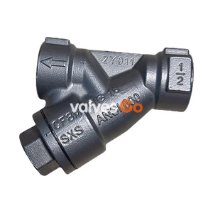
Threaded Connection
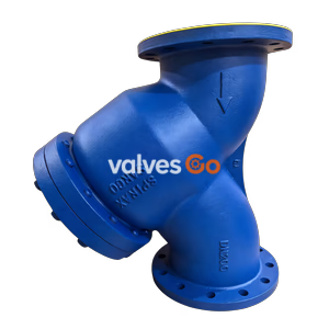
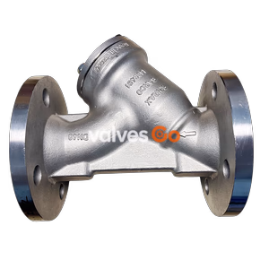
Yoshitake SY-40 series Y-type strainers feature ductile cast iron construction and stainless steel screens. Available in 15A-300A sizes for steam, air, water, and oil applications.
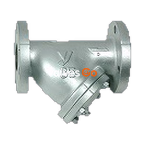
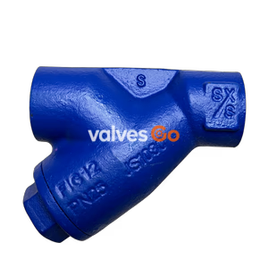
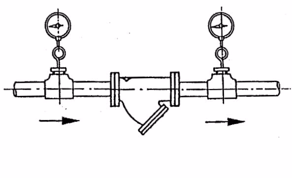
Yoshitake SY-40 series strainers are widely used for dust removal from various types of pipelines. A strainer should be installed upstream of a pressure reducing, temperature regulating, solenoid, or trap valve to protect and maintain it. The series includes the standard SY-40, the corrosion-resistant SY-40C with nylon coating, and the high-pressure SY-40H.
| Model | SY-40 | SY-40C | SY-40H |
|---|---|---|---|
| Nominal Size | 15-300A | 65-150A | 15-150A |
| Application | Steam, air, hot/cold water, oil, non-dangerous fluids | Air, hot/cold water, non-dangerous fluids | Steam, air, hot/cold water, non-dangerous fluids |
| Maximum Pressure | 1.0 MPa | 1.0 MPa | 2.0 MPa |
| Maximum Temperature | 220°C | 60°C | 220°C |
| Body Material | Ductile cast iron | Ductile cast iron (Nylon coated) | Ductile cast iron |
| Screen Material | Stainless steel | Stainless steel | Stainless steel |
| Connection | JIS 10K FF flanged | JIS 10K FF flanged | JIS 20K FF flanged |
| Standard Perforations | φ2.5-4P | φ2.5-4P | φ2.5-4P |
| Standard Mesh | 80 mesh | 60 mesh | 80 mesh |
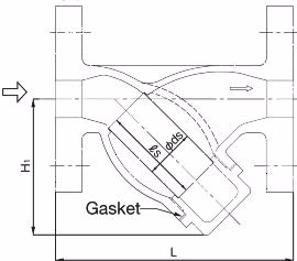
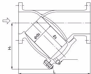
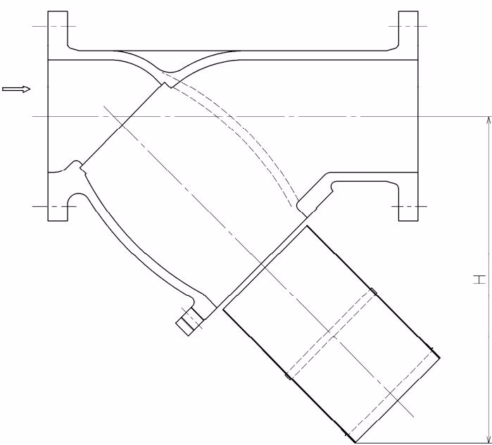
| Nominal Size | L (mm) | H1 (mm) | ds (mm) | ls (mm) | Plug | Weight (kg) |
|---|---|---|---|---|---|---|
| 15A | 130 | 61 | 22 | 40 | - | 1.9 |
| 20A | 140 | 75 | 27 | 56 | - | 2.5 |
| 25A | 160 | 88 | 34 | 66 | - | 4.0 |
| 32A | 175 | 104 | 43 | 76 | - | 5.2 |
| 40A | 190 | 115 | 50 | 85 | R 1/2 | 6.7 |
| 50A | 225 | 140 | 61 | 107 | R 1/2 | 10.2 |
Note: No plug is provided with 15A to 32A models.
| Nominal Size | L (mm) | H1 (mm) | ds (mm) | ls (mm) | Plug | Weight (kg) |
|---|---|---|---|---|---|---|
| 65A | 255 | 167 | 73 | 125 | R 1/2 | 14.5 |
| 80A | 330 | 190 | 88 | 130 | R 1/2 | 18.3 |
| 100A | 370 | 225 | 108 | 180 | R 3/4 | 29.7 |
| 125A | 415 | 263 | 136 | 200 | R 3/4 | 40.5 |
| 150A | 495 | 315 | 160 | 250 | R 3/4 | 66.0 |
| 200A | 565 | 385 | 210 | 300 | R 3/4 | 95.8 |
| 250A | 690 | 460 | 260 | 370 | R 3/4 | 167.5 |
| 300A | 840 | 556 | 315 | 442 | R 3/4 | 286.0 |
Screen: Perforation = φ2.5-4P, Mesh = 80 mesh.
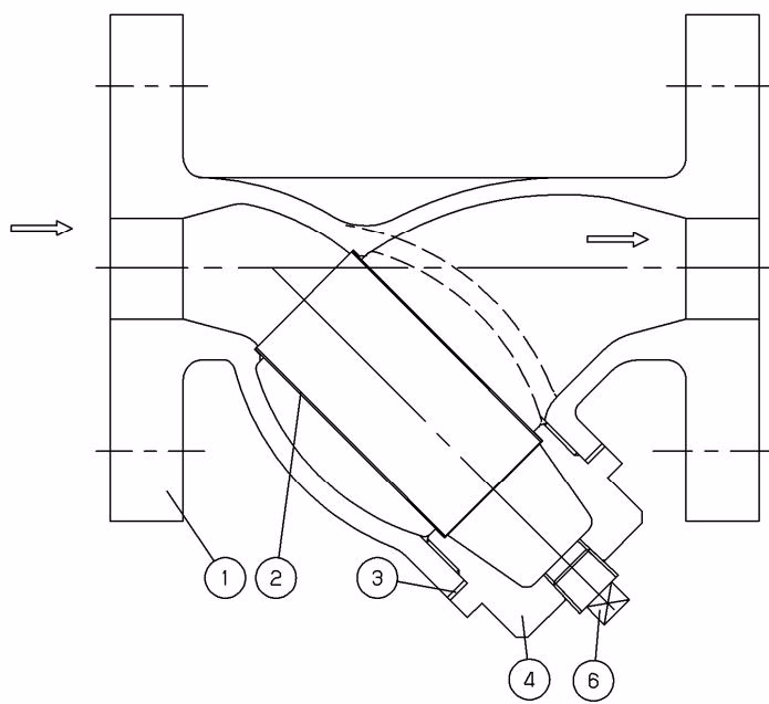
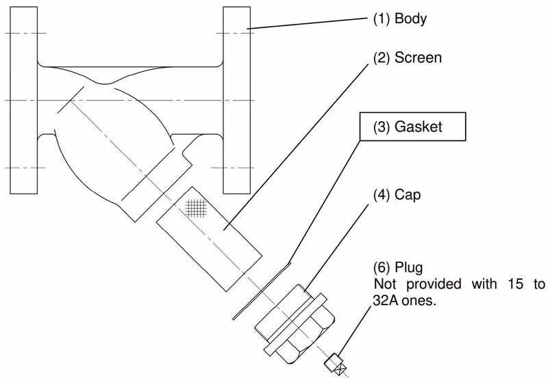
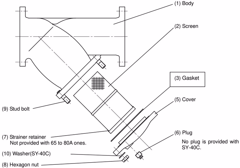
| No. | Part Name | No. | Part Name |
|---|---|---|---|
| 1 | Body | 6 | Plug |
| 2 | Screen | 7 | Strainer retainer |
| 3 | Gasket | 8 | Hexagon nut |
| 4 | Cap | 9 | Stud bolt |
| 5 | Cover | 10 | Washer |
Dust, scale, and other foreign matter from the fluid flowing into the strainer through the inlet port are removed by the screen (2).
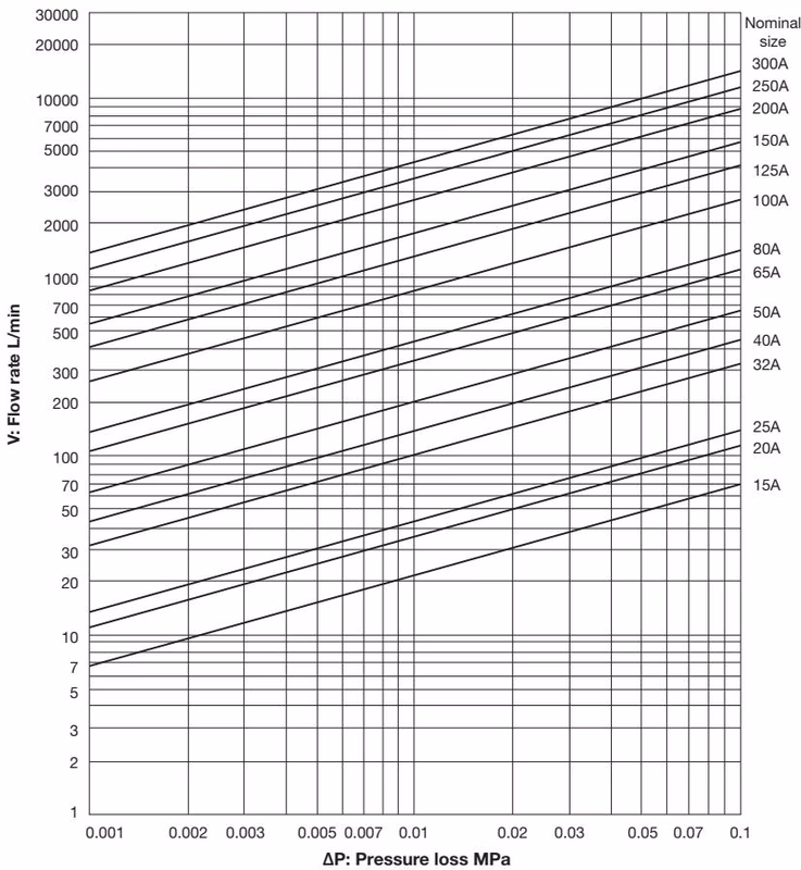
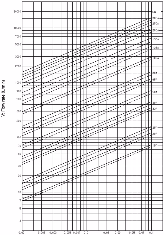
To make the best use of the strainer, select a nominal size equivalent to that of the pipe. Using a smaller nominal size increases the pressure loss. The preferred initial pressure loss is 0.02-0.03 MPa.
Standard Fluid Velocity (JIS F 7101):
| Fluid | Remarks | Standard Flow Velocity |
|---|---|---|
| Saturated steam | Small-diameter / Auxiliary | 15 m/s (10-20) |
| Saturated steam | Large-diameter | 30 m/s (20-40) |
| Superheated steam | φ75 – φ250 | 40 m/s (30-50) |
| Superheated steam | High-grade material | 70 m/s (65-80) |
| Air | Higher pressure (≥1.0 MPa) | 20 m/s (20-25) |
| Air | Lower pressure | 15 m/s (5-15) |
| Water or oil | - | 2 m/s (2-4) |
Installation and Operation Cautions
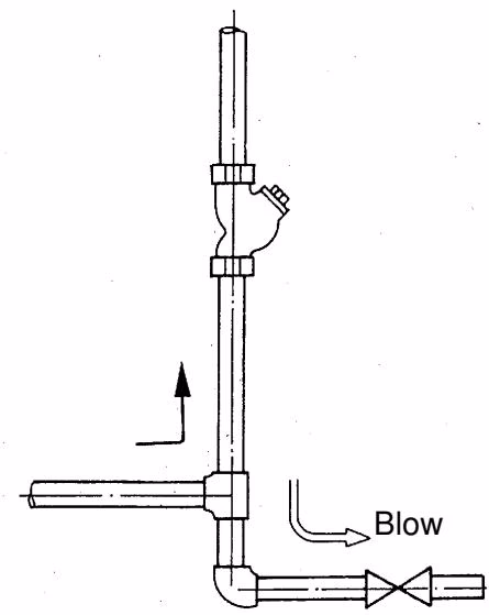
When installing, reserve enough space for screen maintenance and cleaning.
| Nominal Size | H Clearance (mm) | Nominal Size | H Clearance (mm) |
|---|---|---|---|
| 15A | 80 | 80A | 245 |
| 20A | 105 | 100A | 310 |
| 25A | 125 | 125A | 365 |
| 32A | 145 | 150A | 445 |
| 40A | 160 | 200A | 550 |
| 50A | 200 | 250A | 675 |
| 65A | 220 | 300A | 805 |
| Problem | Cause | Solution |
|---|---|---|
| Fluid does not flow. | 1. Screen is clogged. 2. Upstream/downstream stop valves closed. | 1. Overhaul and clean screen. 2. Open the stop valves. |
| Excessive pressure loss | 1. Screen is clogged. 2. Pressure gauge is out of order. 3. Nominal size is too small. | 1. Overhaul and clean screen. 2. Replace pressure gauge. 3. Change to adequate nominal size. |