
All-Stainless Steel Material

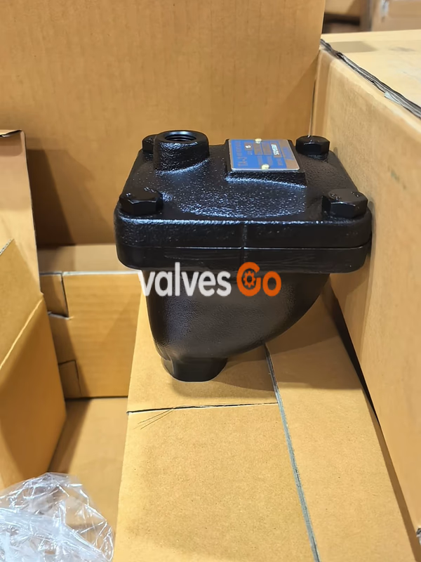
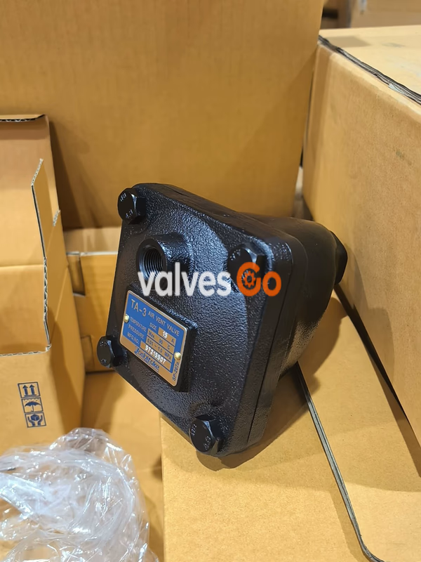
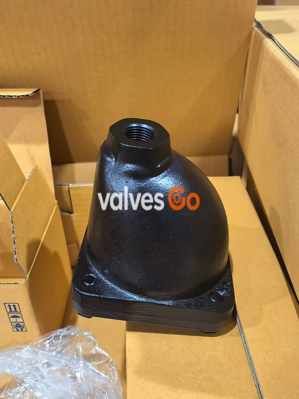
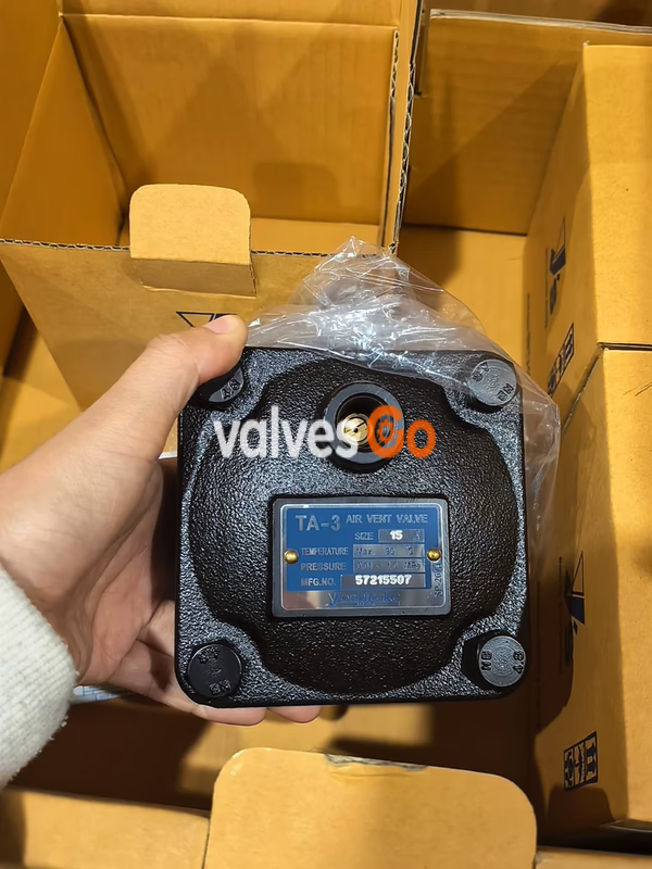
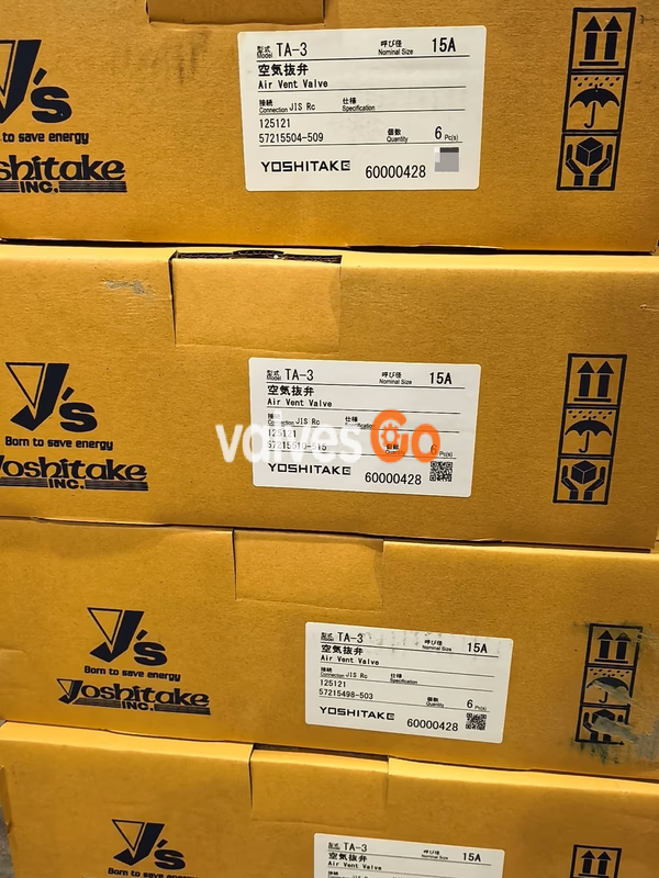
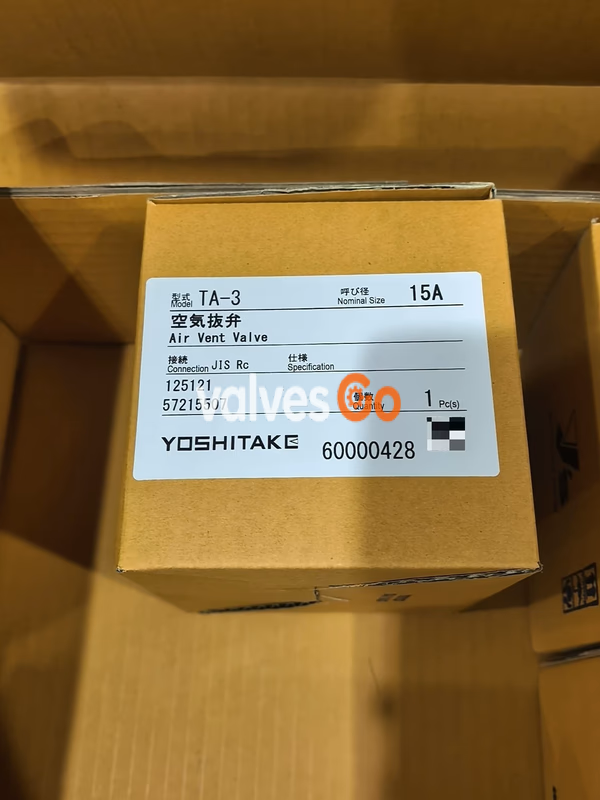
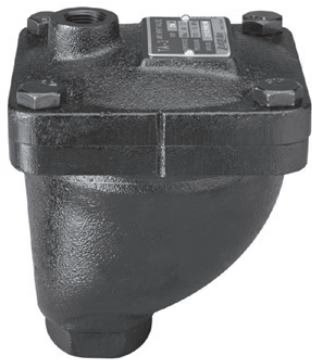
Yoshitake TA-3 air vent valve for cold/hot water and oil. Ductile cast iron body, JIS Rc screwed connection, 0.01-1.0 MPa working pressure, up to 90°C.
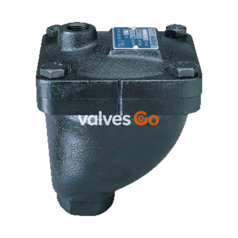
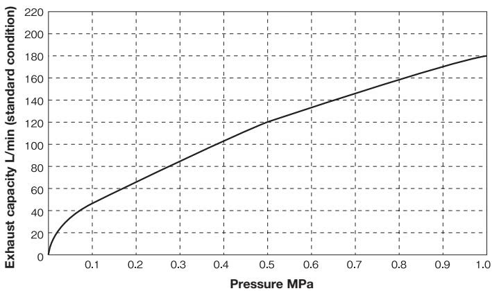
Yoshitake TA-3 is a high-performance air vent valve applicable to a wider pressure range than conventional models, covering from low to high pressures. It is suitable for building equipment, industrial equipment, and building complexes. The valve seat uses synthetic rubber to ensure zero leakage, and the valve body is electrodeposition-coated for rustproofing.
| Model | TA-3 | TA-6 |
|---|---|---|
| Application | Cold and hot water, Oil (Specific gravity: 0.8 or more) | Cold and hot water, Oil (Specific gravity: 0.8 or more) |
| Working pressure | 0.01 - 1.0 MPa | 0.01 - 1.0 MPa |
| Maximum temperature | 90°C | 90°C |
| Material (Body, Cover) | Ductile cast iron (FCD450) | Cast bronze |
| Material (Valve) | Brass | Brass |
| Material (Valve seat) | Brass (with NBR disc) | Brass (with NBR disc) |
| Material (Float) | Stainless steel | Stainless steel |
| Connection | JIS Rc screwed | JIS Rc screwed |
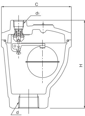
| Nominal size | d | d1 | H (mm) | C (mm) | Weight (kg) |
|---|---|---|---|---|---|
| 15A | Rc 1/2 | Rc 3/8 | 139 | 114 | 2.72 |
| 20A | Rc 3/4 | Rc 3/8 | 139 | 114 | 2.72 |
| 25A | Rc 1 | Rc 3/8 | 143 | 114 | 2.88 |
| 32A | Rc 1-1/4 | Rc 3/8 | 143 | 114 | 2.88 |
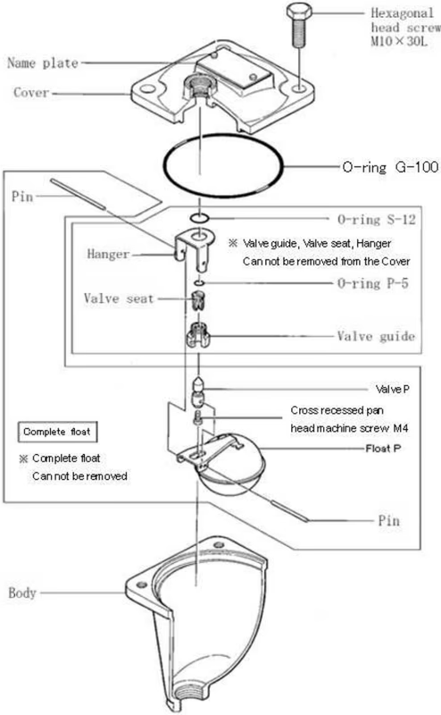
| No. | Parts |
|---|---|
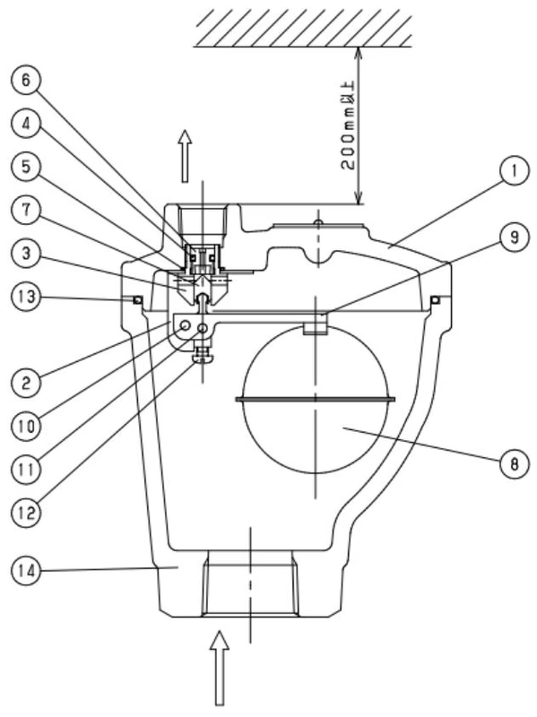
| 1 | Cover |
| 2 | Hanger |
| 3 | Valve guide |
| 4 | O-ring |
| 5 | O-ring |
| 6 | Valve seat |
| 7 | Valve |
| 8 | Float |
| 9 | Arm |
| 10 | Pin |
| 11 | Pin |
| 12 | Cross recessed panhead machine screw |
| 13 | O-ring |
| 14 | Body |
WARNING
TIP
Yoshitake Air & Gas Vents
TA, TAV, and VB series air and vacuum valves for automatic venting, rapid air release, and vacuum protection.
Explore similar products in our catalog