All-Stainless Steel Material

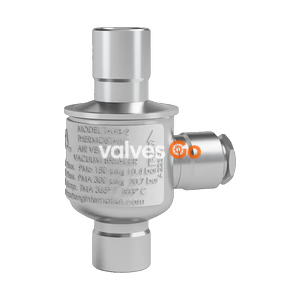
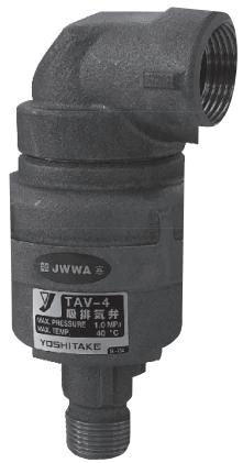
Yoshitake TAV-4 Air Vent Valve with Vacuum Breaker. Designed for city water systems, operating at 0.05-1.0 MPa and 0-40°C. Features cast bronze body, rapid air intake performance, and initial exhaust function.
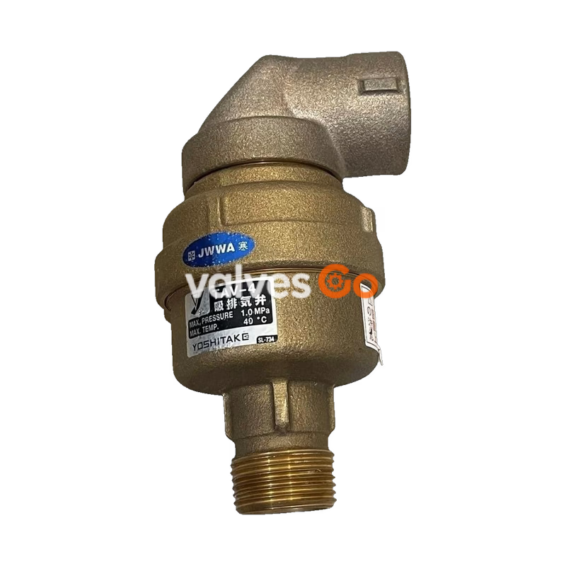
The Yoshitake TAV-4 Air Vent Valve with Vacuum Breaker is primarily installed at the top of water supply vertical pipes in housing complexes and similar applications. This valve exhausts air from vertical piping while water is filling to reduce air discharge from faucets, continuously exhausts accumulated air during normal use to lessen water running resistance, and sucks air from outside the piping to destruct any negative pressure generated inside the system.
| Application | City water (clean water) |
|---|---|
| Working pressure | 0.05-1.0 MPa |
| Intake air quantity (under the pressure difference of 2.9 kPa) | 20A: 15.1 L/sec 25A: 23.4 L/sec |
| Working temperature | 0-40°C (no freeze condition) |
| Body | Cast bronze (NPb-treated) |
| Float | Synthetic resin |
| Exhaust Packing | Synthetic rubber |
| Nominal size | d1 | d2 | H | H1 | W | L | Weight |
|---|---|---|---|---|---|---|---|
| 20A | JIS R 3/4 | JIS Rc 1 | 151 | 130 | φ76 | 49.5 | 1.2 kg |
| 25A | JIS R 1 | JIS Rc 1 | 153 | 132 | φ76 | 49.5 | 1.2 kg |
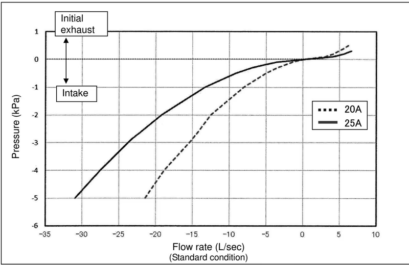
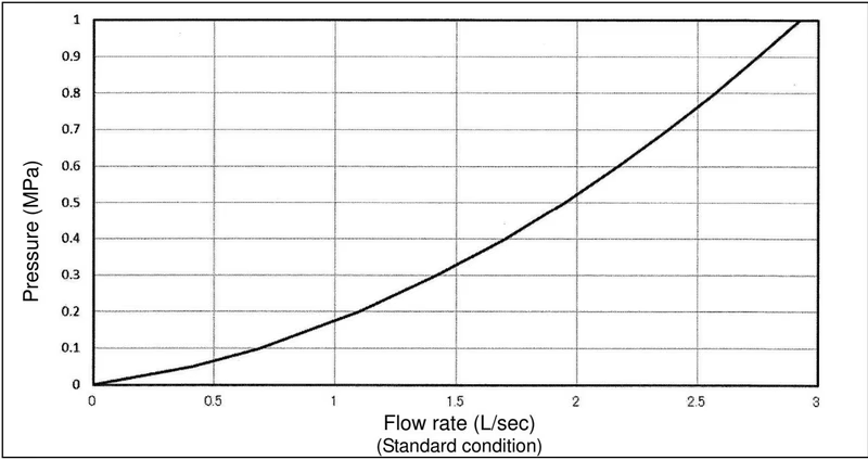
INFO
The values read from the charts should be used as a reference. Ensure a safety factor of at least 20% due to potential fluctuations in piping or usage conditions.
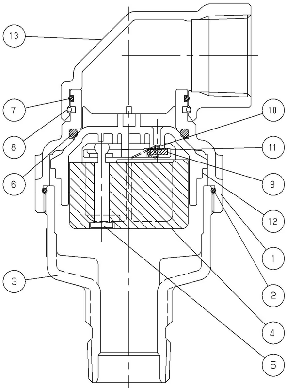
| No. | Part Name | Material | No. | Part Name | Material |
|---|---|---|---|---|---|
| 1 | Bonnet | - | 8 | Ring | Stainless Steel |
| 2 | O ring | NBR | 9 | Exhaust packing | EPDM |
| 3 | Body | - | 10 | Exhaust Spring | Stainless Steel |
| 4 | Float body | - | 11 | Lever board | POM |
| 5 | Float shaft | PE | 12 | Intake valve | POM |
| 6 | O ring | NBR | 13 | Cover | Bronze |
| 7 | O ring | NBR |
When internal pressure of the piping drops below atmospheric pressure due to water stoppage or draining, the product's internal pressure also drops. The intake valve lowers, starting air intake. 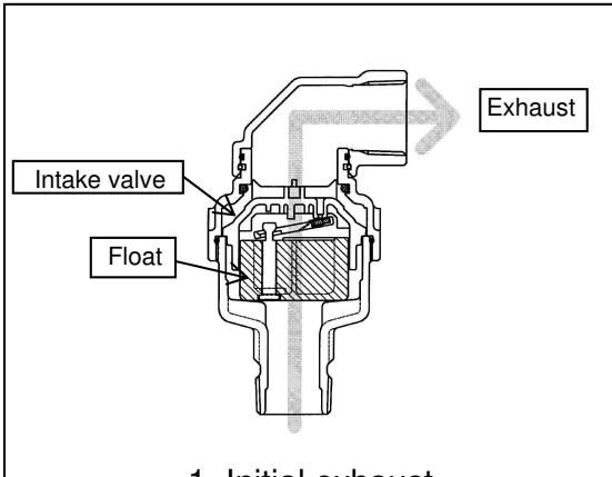
The intake valve is lowered by the weight of the float until water fills the piping and enters the product, exhausting a large quantity of air. When air decreases and water enters, the intake valve floats and closes the opening. 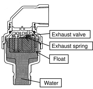
When filled with water, the exhaust valve is closed by water pressure and exhaust spring force. The intake valve is closed by water pressure alone. Because the exhaust valve is independent of the float, its position remains stable despite water pressure fluctuations. 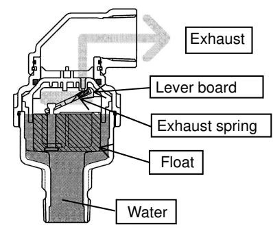
When air enters the water-filled body, the water level lowers, causing the float to descend. The float's weight is applied to the lever board. Once this overcomes the pressure difference and the exhaust spring force, the exhaust valve opens. As air is exhausted and water re-enters, the float rises, removing the weight from the lever board, and the exhaust spring closes the valve. 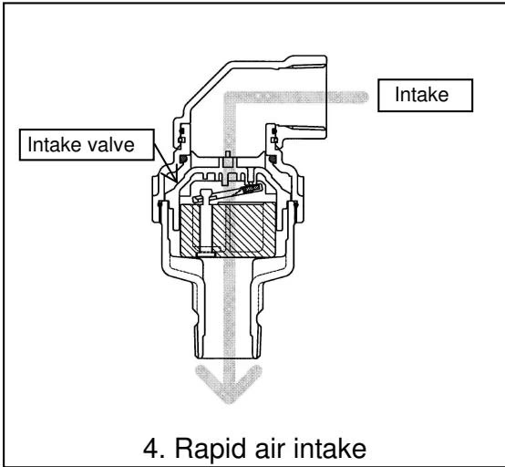
Intake/exhaust valves must be selected based on the intake air quantity required for negative pressure destruction per the nominal size of vertical water pipes.
| Nominal size of vertical pipe | Nagoya City Waterworks & Sewerage Bureau / Urban Renaissance Agency Standard (L/sec) | Bureau of Waterworks, Tokyo Metropolitan Government Standard (L/sec) | Selection of TAV-4 |
|---|---|---|---|
| 20A | 1.5 | 1.5 | 1 piece of TAV-4 20A |
| 25A | 2.5 | 2.5 | 1 piece of TAV-4 20A |
| 32A | 4.0 | 3.5 | 1 piece of TAV-4 20A |
| 40A | 7.0 | 5.5 | 1 piece of TAV-4 20A |
| 50A | 14.0 | 9.0 | 1 piece of TAV-4 20A |
| 75A | 33.4 (2004 L/min) | 15.5 | 1 piece of TAV-4 25A (Tokyo standard) / 2 or more pieces (Nagoya standard) |
| 100A | - | 25.0 | 2 or more pieces |
| 150A | - | 53.0 | 2 or more pieces |
Install the product to satisfy or exceed the required intake air quantity. 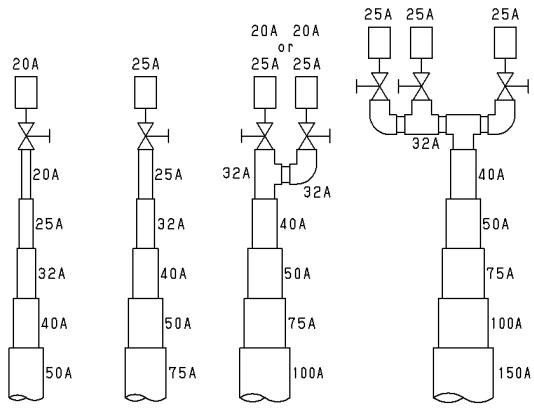
Guide pipe use: 25A steel pipe or 25A PVC is allowed. Total length should be 1 m or less. Only one elbow is permitted. Stop valve must be a gate valve or full-bore ball valve (not a globe valve) with a nominal diameter equal to or larger than the TAV-4. 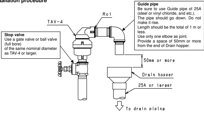
Precautions for Installation
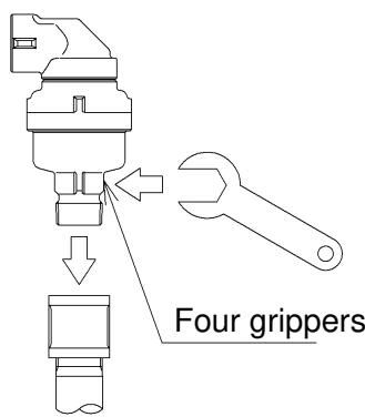
Operating Notes
Yoshitake Air & Gas Vents
TA, TAV, and VB series air and vacuum valves for automatic venting, rapid air release, and vacuum protection.
Explore similar products in our catalog