ENP Nickel Plating

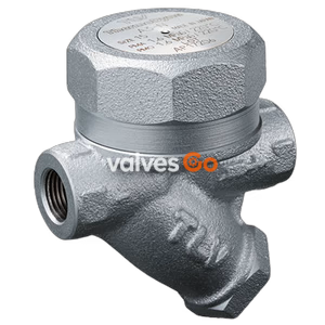
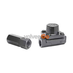
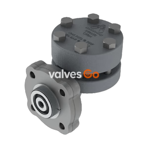
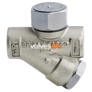
The Yoshitake TSD-42F and TSD-42 are thermodynamic disc steam traps featuring a bimetal ring to prevent air-binding. Constructed from stainless steel, they operate up to 4.2 MPa and 425°C, with a built-in strainer.
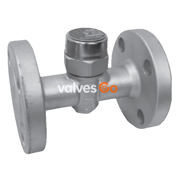
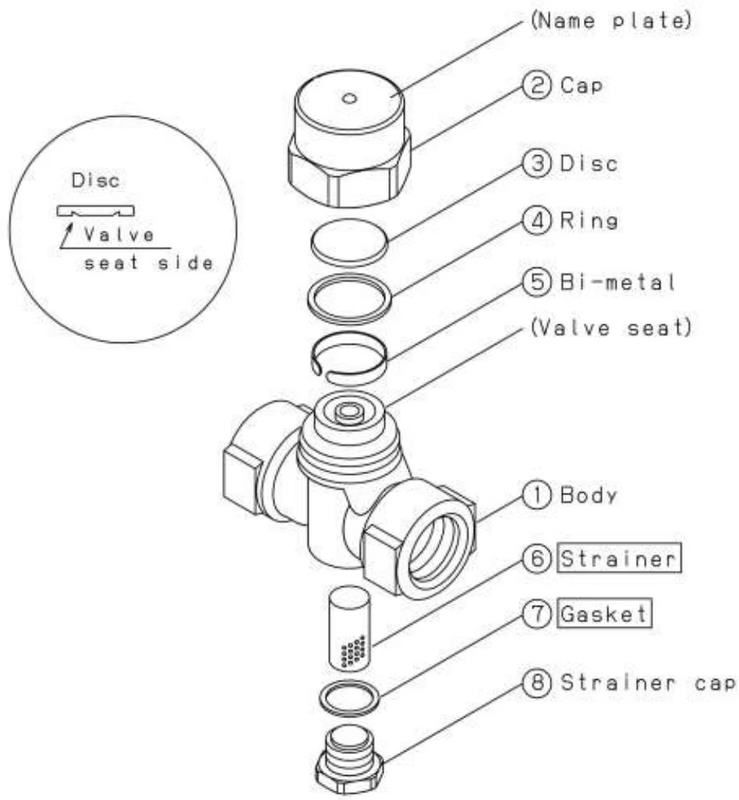
The Yoshitake TSD-42F and TSD-42 are thermodynamic disc steam traps designed for steam condensate applications. Featuring a bimetal ring that solves air-binding problems, these traps ensure a smooth discharge of cold condensate or air at the start of operation, enabling steam equipment to efficiently start running. The main parts are constructed from stainless steel (SCS2A body and SUS420J2 disc/seat with special heat treatment), providing excellent corrosion resistance.
Capable of operating under temperatures up to 425°C and pressures up to 4.2 MPa, the TSD-42 series is suitable for various industries, including heavy, light, and general industrial applications. The traps feature an insulation cover to avoid frequent on-off operation and a built-in strainer, eliminating the need for an external strainer before the trap. Plumbing is easy to perform as they can be installed vertically or horizontally as desired.
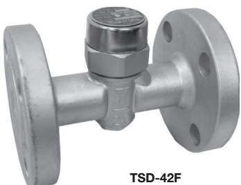
| Model | TSD-42 | TSD-42F |
|---|---|---|
| Nominal Size | 10A - 25A | 15A - 25A |
| Application | Steam condensate | Steam condensate |
| Working Pressure | 0.035 - 4.2 MPa | 0.035 - 4.2 MPa (varies by flange rating) |
| Allowable Back Pressure | 50% or less of inlet pressure | 50% or less of inlet pressure |
| Maximum Temperature | 425°C | 425°C (varies by flange rating) |
| Body Material | Stainless steel (SCS2A) | Stainless steel (SCS2A) |
| Disc, Seat Material | Stainless steel (special heat treatment) | Stainless steel (special heat treatment) |
| Connection | JIS Rc, NPT, BSPT screwed | JIS 10K/20K/30K/40K RF, PN 25/40, ASME 150/300/600lb |
INFO
Relationship between the maximum pressure and the maximum temperature is according to the applicable flange standard pressure-temperature rating (JIS B2220, BS EN 1092-1, ASME B16.5).
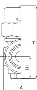
| Nominal size | L (mm) | H (mm) | H1 (mm) | A (mm) | Weight (kg) |
|---|---|---|---|---|---|
| 10A | 78 | 76 | 23 | 32 | 0.65 |
| 15A | 78 | 76 | 23 | 32 | 0.6 |
| 20A | 85 | 79 | 24 | 38 | 0.7 |
| 25A | 95 | 86 | 27.5 | 45 | 0.9 |
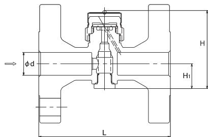
JIS 10K / 20K RF
| Nominal size | d (mm) | L (mm) | H (mm) | H1 (mm) | Weight (kg) |
|---|---|---|---|---|---|
| 15A | 15 | 127 | 76 | 23 | 2.0 |
| 20A | 20 | 131 | 79 | 24 | 2.4 |
| 25A | 25 | 131 | 86 | 27.5 | 3.5 |
JIS 30K RF
| Nominal size | d (mm) | L (mm) | H (mm) | H1 (mm) | Weight (kg) |
|---|---|---|---|---|---|
| 15A | 15 | 135 | 76 | 23 | 3.4 |
| 20A | 20 | 135 | 79 | 24 | 3.6 |
| 25A | 25 | 139 | 86 | 27.5 | 4.6 |
JIS 40K RF
| Nominal size | d (mm) | L (mm) | H (mm) | H1 (mm) | Weight (kg) |
|---|---|---|---|---|---|
| 15A | 15 | 139 | 76 | 23 | 3.6 |
| 20A | 20 | 139 | 79 | 24 | 4.0 |
| 25A | 25 | 144 | 86 | 27.5 | 5.0 |
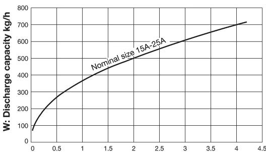
To select the product size, secure a safety factor of 4 to 5. For example, if you need a steam trap with a capacity of 100 kg/h, a trap with a capacity of 400 to 500 kg/h should be selected for maximum efficiency.
The back pressure (outlet pressure) should be considered when selecting discharge capacity, as it depends on the operating differential pressure (the difference between the inlet and outlet pressure).
| Phase | Description | Diagram |
|---|---|---|
| 1. Start-up | At start-up, the bi-metal is cooled in a shrunk and closed condition, keeping the disc lifted up. Incoming air and condensate are discharged smoothly without air-induced troubles. | 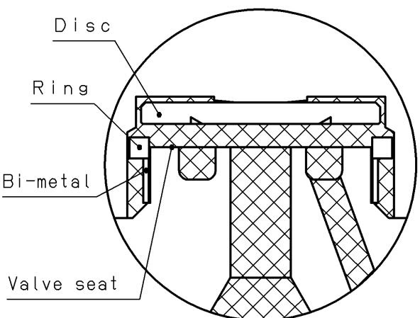 |
| 2. Closing | When hot condensate flows in, the bi-metal expands, slipping down the slant of the valve seat. Flash steam moving at high velocity under the disc creates a low-pressure area, forcing the disc down until it seats. | 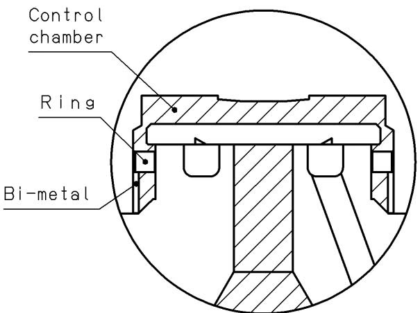 |
| 3. Inflow | Condensate flowing into the trap reduces temperature, causing the steam inside the control chamber to condense. This pressure drop decreases the downward force on the disc. | 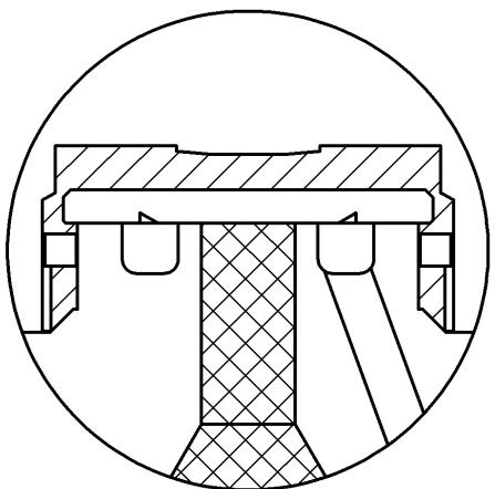 |
| 4. Opening | When the downward force becomes lower than the upward force from the jetting-out port, the disc is lifted to the opened position and condensate is discharged. | 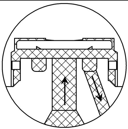 |
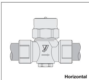
The trap can be installed vertically or horizontally.
WARNING
To discharge condensate to the atmosphere, lead the outlet to a place where there is no possibility of physical damage. Failure to follow this notice may result in injury and scalds when condensate blows out.
| Description | Correct |
|---|---|
| If installed close to a regulating valve, place the product at the inlet side. | 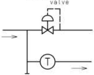 |
| To discharge condensate from the steam main, install so condensate discharges from the bottom (drain-pot). | 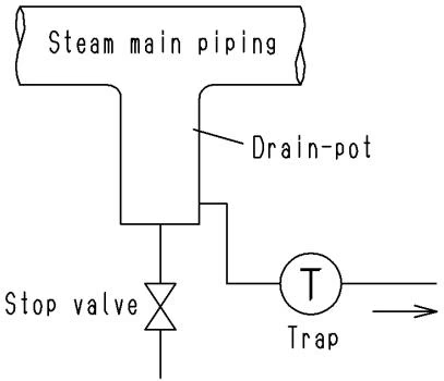 |
| The product should be installed below a device which causes condensate. | 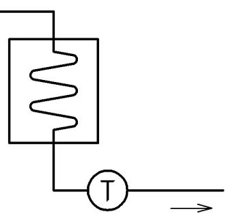 |
| To discharge condensate from more than one device, install a trap for each device independently. | 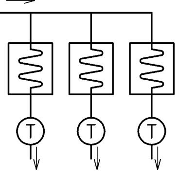 |
| The diameter of the collecting pipe should be more than the summation of sectional areas of discharge pipes. Install check valves. | 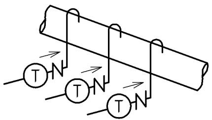 |
| To recover condensate, connect discharge pipes at the top of the collecting pipe. | 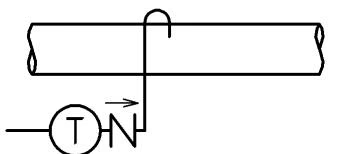 |
| End portion of discharge pipe should be off the water surface in the pit. | 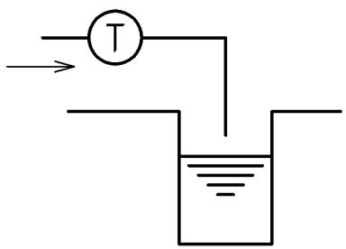 |
WARNING
Completely discharge internal pressure of the product, piping, and equipment, and cool down the product prior to disassembly or maintenance.
| Trouble | Cause | Remedy |
|---|---|---|
| Condensate is not discharged | 1. Blockage in valve seat discharge hole. 2. Strainer is clogging. 3. Breakage from abnormal pressure (freezing/water hammer). 4. Steam locking. | 1. Disassemble and clean. 2. Disassemble and clean. 3. Replace product. 4. Change piping layout. |
| Continuous blowout | 1. Foreign substances on disc/seat. 2. Abrasion/scratches on disc/seat. 3. Back pressure exceeds max allowable. 4. Applied pressure is less than minimum. | 1. Disassemble and clean. 2. Replace product. 3. Keep back pressure within limits. 4. Replace with appropriate model. |
| Steam leakage | 1. Loosen joint between body and cap. 2. Loosen joint between body and strainer cap. 3. Breakage from abnormal pressure. | 1. Retighten cap. 2. Replace gasket and retighten strainer cap. 3. Replace product. |
| No-load operation | 1. Abrasion/scratches on disc/seat. 2. Foreign substances on disc/seat. | 1. Replace product. 2. Disassemble and clean. |
Yoshitake Steam Traps / Thermodynamic Steam Traps
TD and TSD series thermodynamic steam traps for condensate drainage from steam mains and equipment.
Explore similar products in our catalog