


PN16

Yoshitake TSF-8 float steam trap with thermostatic air vent. Designed for steam condensate discharging, max 2.1 MPa, up to 220°C, featuring a built-in strainer and stainless steel internals.
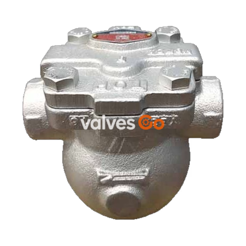
Yoshitake TSF-8 and TSF-8F series are mechanical float steam traps designed to effectively discharge steam condensate without retention. Utilizing the difference in specific gravity between steam and condensate, these traps ensure reliable operation across varying loads. The series is equipped with a built-in thermostatic air vent to automatically discharge initial air and non-condensable gases, preventing air binding. With all main internal components constructed from stainless steel and a built-in strainer to protect against foreign substances, the TSF-8 series delivers excellent corrosion resistance and long-term durability in steam applications.
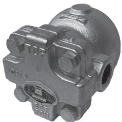
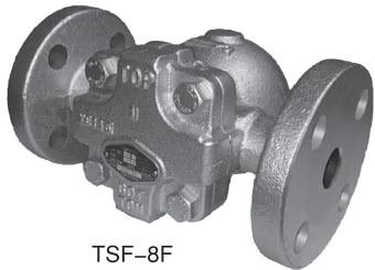
| Model | TSF-8 | TSF-8F |
|---|---|---|
| Nominal size | 15A, 20A, 25A | 15A, 20A, 25A |
| Application | Steam condensate | Steam condensate |
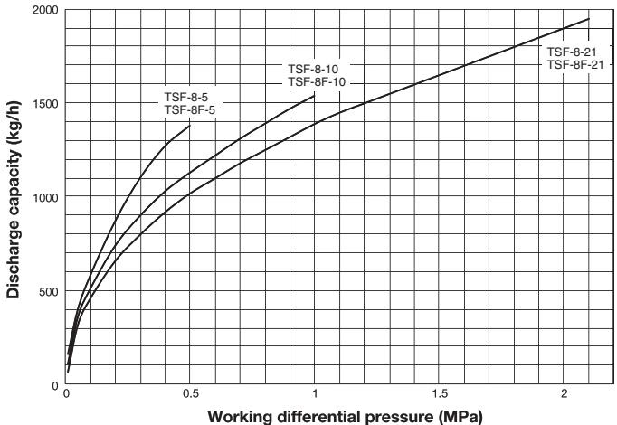
| Working pressure (Max. working differential pressure) | TSF-8-5: 0.01-0.5 MPa (0.5 MPa) TSF-8-10: 0.01-1.0 MPa (1.0 MPa) TSF-8-21: 0.01-2.1 MPa (2.1 MPa) | TSF-8F-5: 0.01-0.5 MPa (0.5 MPa) TSF-8F-10: 0.01-1.0 MPa (1.0 MPa) TSF-8F-21: 0.01-2.1 MPa (2.1 MPa) |
| Max. temperature | 220℃ | 220℃ |
| Body Material | Ductile cast iron | Ductile cast iron |
| Float Material | Stainless steel | Stainless steel |
| Valve, valve seat Material | Stainless steel | Stainless steel |
| Connection | JIS Rc screwed, NPT screwed | JIS 10K/20K FF, EN PN25 RF, ASME 150lb/300lb RF |
TSF-8 (Screwed)
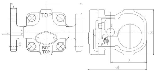
| Nominal size | d | L | A | A1 | H | Weight (kg) |
|---|---|---|---|---|---|---|
| 15A | Rc 1/2 | 121 | 147 | 90 | 113 | 3.7 |
| 20A | Rc 3/4 | 121 | 147 | 90 | 113 | 3.7 |
| 25A | Rc 1 | 145 | 147 | 90 | 113 | 4.1 |
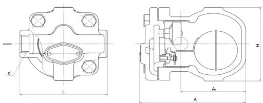
TSF-8F (Flanged)
| Nominal size | d | L | A | A1 | H | Weight (kg) |
|---|---|---|---|---|---|---|
| 15A | 15 | 175 | 147 | 90 | 113 | 5.4 |
| 20A | 20 | 195 | 147 | 90 | 113 | 6.0 |
| 25A | 25 | 215 | 147 | 90 | 113 | 6.3 |
The discharge capacity shown on the chart below is the maximum value. In designing a system, select a steam trap with a sufficient safety factor (more than two times the regular level). If a discharge capacity of 500 kg/h is required, select a steam trap capable of discharging more than 1,000 kg/h.
At start-up, since the float is down, the valve is closed. In this state, air in the system and piping is discharged out through the air vent which is opened. When condensate flows into the product, the float lifts up and opens the valve, and then discharges condensate. Air is continuously discharged out from the air vent. 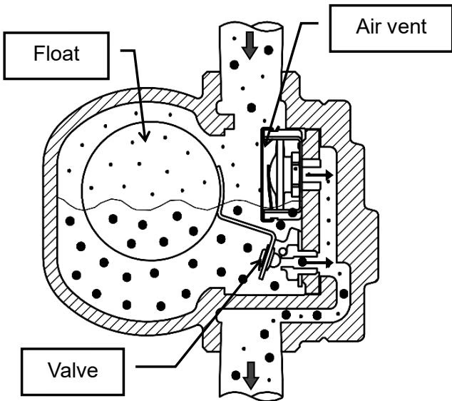
When steam flows into the product, internal pressure of the air vent rises by steam temperature, and the air vent closes. According to the amount of condensate inflow, the float position moves up and down changing the opening degree of the valve, and thus condensate is continuously discharged. The float moves down and the valve closes when condensate inflow stops. 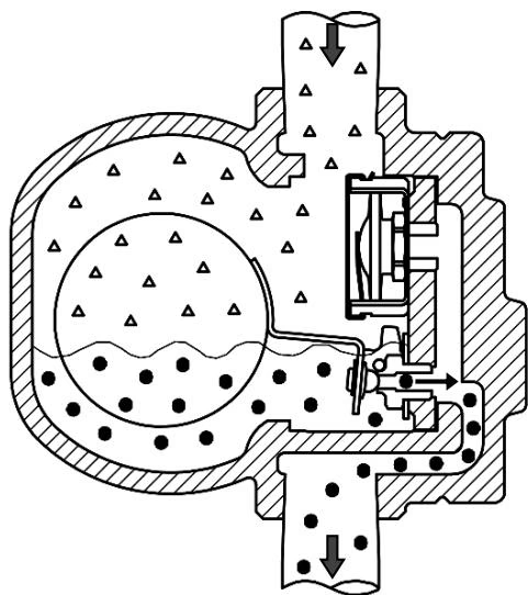
When air or non-condensable gas flows into the product, it accumulates in the upper part of the product. When temperature of air or noncondensable gas decreases with condensate inflow, the air vent opens and discharges it to outside of the product. 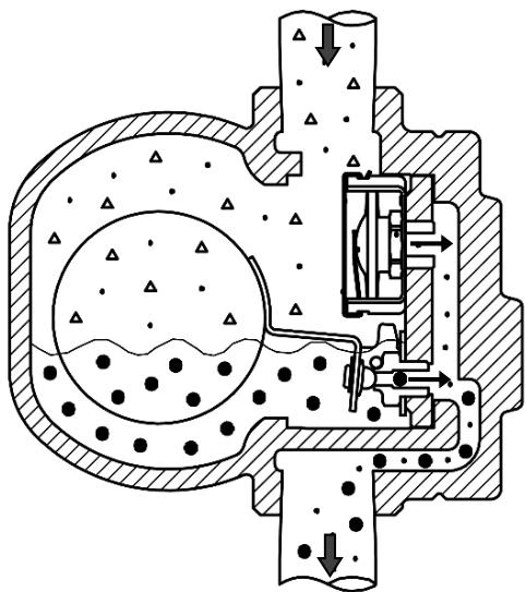
Then, operations 2 and 3 repeat according to the inflow amount of condensate and air. 
Flow Direction Options
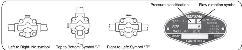
The standard flow direction of TSF-8 is left to right. However, flow direction from right to left and top to bottom is also available. Please specify the required flow direction when ordering.
| Flow direction | Symbol |
|---|---|
| Left to Right (Pre-set) | Blank |
| Top to Bottom | V |
| Right to Left | R |
Installation Best Practices
Operational Cautions
Yoshitake Steam Traps / Float Steam Traps
TF and TSF series float steam traps for continuous condensate drainage in steam systems.





