Repairable

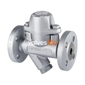
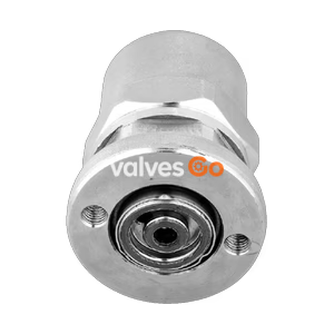
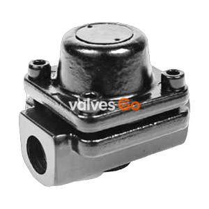
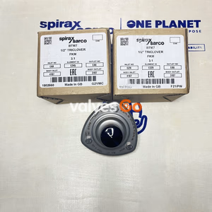
Armstrong WT Series thermostatic wafer steam traps (WT-1, WT-3, WT-2000) for steam tracers and superheated drip service. Features non-welded wafer design.
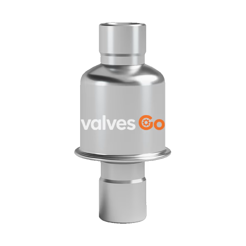
Armstrong WT Series thermostatic wafer steam traps are designed for steam tracing and superheated drip applications. The series features an exclusive non-welded wafer design that eliminates problems associated with weld stress and thin-walled enclosures such as bellows or welded diaphragms, making them highly resistant to water hammer.
Application Note
Since the normal operation of all suppressed temperature-discharge (subcooling) steam traps is to back up condensate, they should not be used on drip legs for saturated steam service, heating, or process equipment. Exercise care in the maintenance of any thermostatic wafer trap with a small discharge area susceptible to clogging.
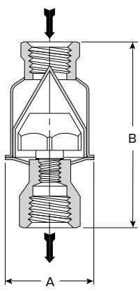 Model WT-1 Trap
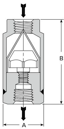 Model WT-3 Trap
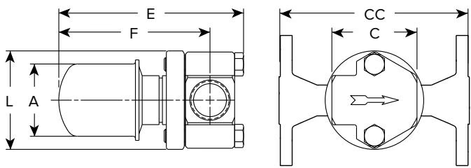 Model WT-2000 with Standard Connector
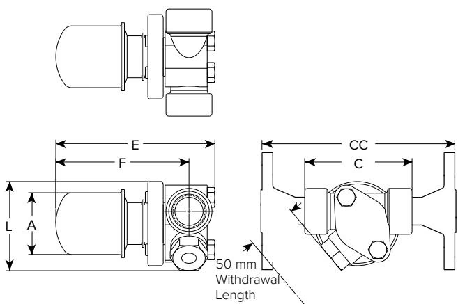 Model WT-2000 with IS-2 Connector with Integral Strainer
| Feature | WT-1 | WT-2000 | WT-3 |
|---|---|---|---|
| Design | Welded | Welded | Welded |
| Connections | Screwed (NPT/BSPT), Socketweld | Screwed (NPT/BSPT), Socketweld, Flanged | Screwed (NPT/BSPT), Socketweld |
| Body & Cap Material | ASTM A240—304L Stainless Steel | ASTM A240—304L Stainless Steel | Carbon Steel C-1018 |
| Capsule Wafer | Hastelloy | Hastelloy | Hastelloy |
| Capsule Body & Cap | Stainless Steel 303 | Stainless Steel 303 | Stainless Steel 303 |
| Max Allowable Pressure | 28 bar @ 343°C (400 psig @ 650°F) | 28 bar @ 343°C (400 psig @ 650°F) | 41 bar @ 399°C (600 psig @ 750°F) |
| Max Operating Pressure | 28 bar (400 psig) | 28 bar (400 psig) | 41 bar (600 psig) |
Maximum back pressure: 99% of inlet pressure.
Capacities will vary with the degree of subcooling. When greater capacities are required, the trap will automatically adjust to the load, up to the maximum (cold water) capacity shown, by increasing the amount of subcooling.
| Differential Pressure (bar) | Cold Water Start-Up 21°C (kg/h) | Hot Water Start-Up 100°C (kg/h) | Operating Condensate 10°C Below Saturation (kg/h) |
|---|---|---|---|
| 0.35 | 54 | 45 | 4.5 |
| 0.7 | 68 | 77 | 5.9 |
| 1.4 | 145 | 113 | 8.2 |
| 2.0 | 177 | 136 | 9.1 |
| 3.0 | 191 | 159 | 10.9 |
| 3.5 | 222 | 181 | 11.8 |
| 5.0 | 259 | 218 | 13.6 |
| 7.0 | 295 | 263 | 15.9 |
| 10.5 | 318 | 318 | 18.1 |
| 14.0 | 408 | 363 | 20.9 |
| 17.0 | 454 | 431 | 22.7 |
| 21.0 | 476 | 465 | 25.4 |
| 24.0 | 522 | 544 | 28.6 |
| 28.0 | 590 | 567 | 31.8 |
Capacities based on differential pressure with no back pressure.
Steam trap installation is critical from both a performance and maintenance aspect. Installation of the trap is simplified if you follow these guidelines:
In superheat drip applications (Model WT-3 Only), what little condensate there is usually forms in drip legs to the traps and in the traps themselves, rather than in the main or branch piping. Therefore, providing drip legs of adequate length and diameter is essential to the successful operation of the wafer trap.
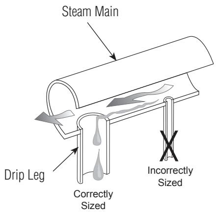 Figure 1. Drip Leg Sizing
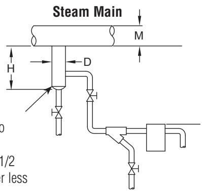 Figure 2. Trap Draining Drip Leg on Steam Main
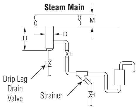 Figure 3. Trap Draining Drip Leg at Riser
Drip Leg Recommendation
The properly sized drip leg will capture condensate. Too small a drip leg can actually cause a venturi "piccolo" effect where pressure drop pulls condensate out of the drip leg and trap. Drip leg should be the same as the header diameter up to 4" (100 mm). Above 4" (100 mm), use 1/2 header size, but never less than 4" (100 mm).
High pressure drip traps should be tested at least three times per year. Tracer traps should be tested yearly on applications up to 100 psi (6.8 bar), twice yearly for pressures from 101-450 psi (6.9 - 31 bar), and three times per year for pressures above 450 psi (31 bar).
When the steam trap is suspected of malfunctioning, it can be checked by observing the discharge of the trap. The discharge of a wafer trap is either intermittent or modulating, depending on the load. If the trap is blowing live steam, remove the trap from the line, back flush it with compressed air or water, re-install it and check it again for normal operation.
Explore similar products in our catalog