

PN16

BURKERT 20009661 (Type 7012) is a direct-acting 3/2-way normally closed plunger solenoid valve with brass body, NPT 1/8 ports, DN 1.6 mm orifice, FKM seals, 24 V DC coil, and 0–7.5 bar operating pressure range.
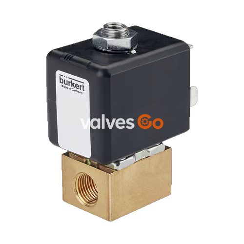
BURKERT 20009661 (Type 7012) is a direct-acting 3/2-way plunger solenoid valve engineered for blocking, dosing, filling, and venting neutral gaseous and liquid media such as compressed air, water, hydraulic oil, and technical vacuum. Configured in Circuit Function C (normally closed), the valve maintains pressure port 1 (P/NC) shut while connecting outlet port 2 (A/OUT) to exhaust port 3 (R/NO) in the de-energized state. Upon electrical actuation, the internal plunger lifts against the core spring, opening flow from port 1 to port 2 while isolating exhaust port 3.
Constructed with a brass valve body, internal NPT 1/8 process connections, and an internal orifice of DN 1.6 mm (1/16"), the unit operates across a pressure span from 0.00 bar up to 7.50 bar (0 to 109 psi) without requiring differential pilot pressure. The stopper and core guide tube are welded together to increase pressure resistance and internal leak tightness. The valve is driven by a 24 V DC epoxy-encapsulated coil (insulation class H) featuring a form B plug connection according to industrial standards, achieving an ingress protection rating of IP65 when coupled with an appropriate cable plug.
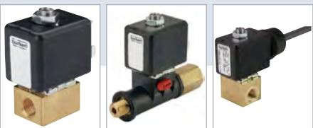
| Specification Parameter | Value |
|---|---|
| Manufacturer Type | 7012 |
| Ident Number (Article / SKU) | 20009661 |
| Circuit Function | C (3/2-way, direct-acting, normally closed) |
| Fluidic Ports | 3 ports, 2 switching positions |
| Nominal Orifice (DN) | 1.6 mm (1/16") |
| Flow Factor Kv (Water) | 0.06 m³/h |
| Flow Coefficient Cv (Water) | 0.07 gpm |
| Operating Pressure Range | 0.00 – 7.50 bar (0 – 109 psi) |
| Port Connection | NPT 1/8 internal thread |
| Nominal Operating Voltage | 24 V DC (tolerance ±10%) |
| Nominal Power Consumption | 7 W cold, 5.5 W warm (DC) |
| Duty Cycle | 100% ED continuous operation |
| Switching Time (DIN ISO 12238:2001) | Opening: 8–12 ms; Closing: 8–12 ms |
| Medium Temperature Range | -10 °C to +100 °C (+14 °F to +212 °F) |
| Ambient Temperature Range | -10 °C to +55 °C (up to +75 °C depending on coil power) |
| Maximum Medium Viscosity | 21 mm²/s (21 cSt) |
| Body Material | Brass |
| Seat & External Seal Material | FKM (fluororubber) |
| Solenoid Thermal Insulation Class | Epoxy coil class H |
| Electrical Connection Sort | Plug pattern form B according to industrial standard |
| Protection Type | IP65 (with properly attached cable plug) |
| Conformity & Certifications | cURus Recognized (UL 429, CAN/CSA-C22.2 No. 139), CE |
BURKERT 20009661 is designated as Circuit Function C (CF C), functioning as a direct-acting three-way normally closed valve. The flow path is routed below the valve seat.
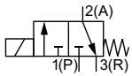
Every fluid-wetted and structural component in the Type 7012 standard variant is selected for mechanical endurance and chemical compatibility with neutral industrial media.
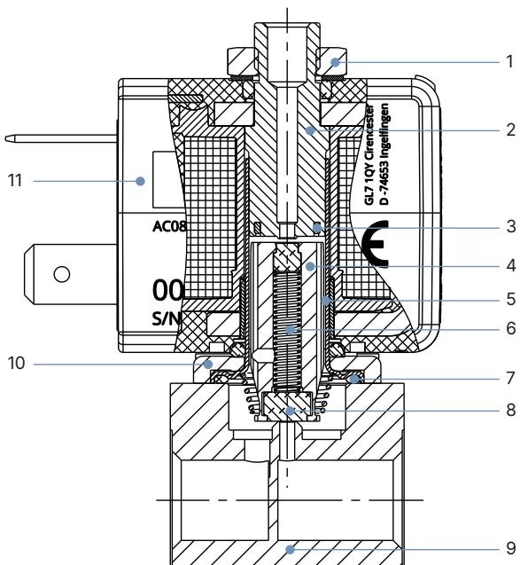
| Item | Component | Material |
|---|---|---|
| 1 | Lock nut | DIN 176, surface thick-film passivated (KOSA0101) |
| 2 | Stopper | Stainless steel 1.4113 / AISI 434 |
| 3 | Shading ring | Copper (silver optional) |
| 4 | Core (plunger) | Stainless steel 1.4113 / AISI 434 |
| 5 | Core guide tube | Stainless steel 1.4303 / AISI 305L (welded to stopper) |
| 6 | Core return spring | Stainless steel 1.4310 / AISI 301 |
| 7 | Housing O-ring | FKM (fluororubber) |
| 8 | Seat seal | FKM (fluororubber) |
| 9 | Valve body | Brass |
| 10 | Flange plate | Surface thick-film passivated (KOSA0101) |
| 11 | Solenoid coil body | Epoxy encapsulation |
The standard threaded variant features a compact footprint. For the NPT 1/8 brass body configuration, the unit weight is approximately 146 g (with 24.5 mm coil).
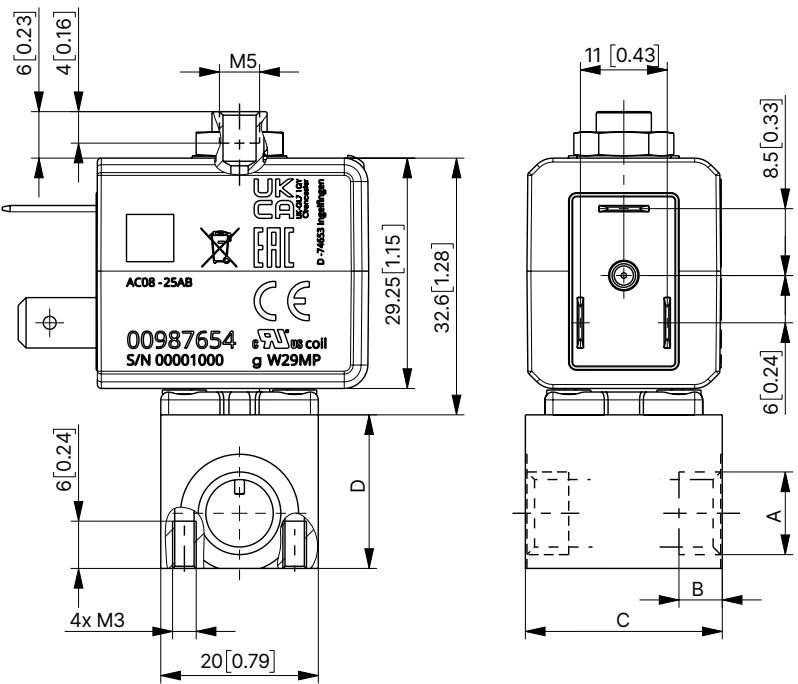
| Port Connection | Thread Depth A [mm] | Thread Depth A [in] | Body Width B [mm] | Body Width B [in] | Body Length C [mm] | Body Length C [in] | Port Center Height D [mm] | Port Center Height D [in] |
|---|---|---|---|---|---|---|---|---|
| M5 | 5 | 0.19 | 20 | 0.78 | 14 | 0.55 | — | — |
| G 1/8 | 8 | 0.31 | 25 | 0.98 | 19.5 | 0.74 | — | — |
| NPT 1/8 | 7 | 0.31 | 25 | 0.98 | 19.5 | 0.74 | — | — |
Port connections on the body correspond to the circuit function markings cast into the valve housing.
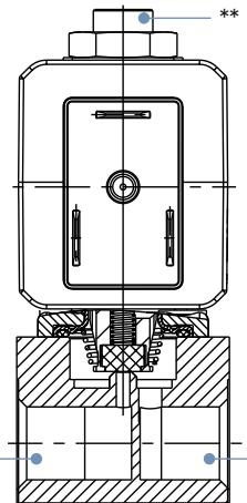
| Circuit Function | Connection Position * | Connection Position ** | Connection Position *** |
|---|---|---|---|
| Function C (WW C) | 1 (P) - Pressure Inlet | 3 (R) - Exhaust / Return | 2 (A) - Working Outlet |
| Function D (WW D) | 3 (R) - Exhaust / Return | 1 (P) - Pressure Inlet | 2 (B) - Working Outlet |
| Function A (WW A) | 1 (P) - Pressure Inlet | To lock (plugged) | 2 (A) - Working Outlet |
| Function B (WW B) | To lock (plugged) | 2 (B) - Working Outlet | 1 (P) - Pressure Inlet |
BURKERT 20009661 utilizes contact pins arranged according to industrial standard form B (contact gap 11 mm). The valve is delivered without a cable plug. To complete the electrical installation and maintain IP65 sealing, pair the valve with a Type 2507 cable plug.
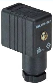
| Plug Model | Circuit Configuration | Voltage Rating | Article Number |
|---|---|---|---|
| Type 2507 Form B | Without wiring (Standard) | 2...250 V AC/DC | 423845 |
| Type 2507 Form B | With LED status indicator | 24 V AC/DC | 423849 |
| Type 2507 Form B | With LED and free-wheeling diode | 12...24 V AC/DC | 423851 |
| Type 2507 Form B | With rectifier, LED, and varistor | 2...250 V AC/DC | 423854 |
| Type 2507 Form B | With rectifier, LED, and varistor | 12...24 V AC/DC | 423853 |
Cable Plug Delivery
Each Type 2507 cable plug assembly includes a flat elastomer gasket and a center fastening screw. The fastening screw must be tightened to a maximum torque of 0.3 Nm to safeguard terminal threads.
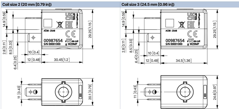
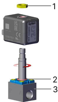
The solenoid coil can be indexed in four directions at 90° intervals (or two 180° positions during manifold block installations) to facilitate cable dressing.
Pressure and High-Voltage Hazards
Isolate the system pressure and depressurize all connected process lines before attempting mechanical installation or disassembly. Disconnect the power supply and prevent accidental reactivation before touching electrical terminals. Prolonged activation causes elevated coil surface temperatures; do not handle hot coils with bare hands.
Operating Restrictions
Piping & Filtration Recommendation
Type 7012 valves operate maintenance-free under specified medium and ambient limits. When servicing or replacing worn subassemblies, only genuine BURKERT spare parts should be utilized.
Explore similar products in our catalog


