

PN16

BURKERT 20014860 is an AirLINE Type 8652 16-slot pneumatic valve island with stainless steel AirLINE Quick plate, 32 digital inputs, Industrial Ethernet gateway, and SIA safety shut-off valve.
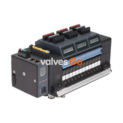
BURKERT 20014860 is an AirLINE Type 8652 pneumatic valve island engineered for process automation environments, preconfigured with 16 valve slots and an AirLINE Quick adapter plate constructed from stainless steel 1.4301. The unit integrates 12 active pneumatic valve stations comprising one SIA safety shut-off valve (2x 3/2-way CF-C) and eleven standard 2x 3/2-way CF-C valves, supplemented by four blind plates for future expansion. All pneumatic connections are executed in stainless steel 1.4401, featuring D10 push-in fittings for supply air and D6 push-in fittings for working ports.
Communication and diagnostics are handled through an integrated Type ME43 Industrial Ethernet gateway supporting PROFINET IO, EtherNet/IP, Modbus TCP, EtherCAT, and CC-Link IE Field Basic over dual RJ45 ports. Diagnostic status is visualized on an integrated LC display with clear text messages and status symbols. The electrical configuration features four 8DI electronic modules delivering 32 digital inputs for direct feedback from limit switches and position sensors without additional distributed I/O hardware.

Article number 20014860 has a factory-defined mechanical and pneumatic structure. The 16 valve slots are occupied by Type 6534 solenoid valve modules and blanking plates as defined below:
| Valve Position | Component Designation | Circuit Function | Description |
|---|---|---|---|
| Position 1 | Type 6534 SIA | 2x 3/2-way CF-C SIA | Safety shut-off valve, normally closed, external potential-free shut-off terminal |
| Position 2 | Type 6534 Standard | 2x 3/2-way CF-C | Standard double 3/2-way solenoid valve, normally closed |
| Position 3 | Type 6534 Standard | 2x 3/2-way CF-C | Standard double 3/2-way solenoid valve, normally closed |
| Position 4 | Type 6534 Standard | 2x 3/2-way CF-C | Standard double 3/2-way solenoid valve, normally closed |
| Position 5 | Type 6534 Standard | 2x 3/2-way CF-C | Standard double 3/2-way solenoid valve, normally closed |
| Position 6 | Type 6534 Standard | 2x 3/2-way CF-C | Standard double 3/2-way solenoid valve, normally closed |
| Position 7 | Type 6534 Standard | 2x 3/2-way CF-C | Standard double 3/2-way solenoid valve, normally closed |
| Position 8 | Type 6534 Standard | 2x 3/2-way CF-C | Standard double 3/2-way solenoid valve, normally closed |
| Position 9 | Type 6534 Standard | 2x 3/2-way CF-C | Standard double 3/2-way solenoid valve, normally closed |
| Position 10 | Type 6534 Standard | 2x 3/2-way CF-C | Standard double 3/2-way solenoid valve, normally closed |
| Position 11 | Type 6534 Standard | 2x 3/2-way CF-C | Standard double 3/2-way solenoid valve, normally closed |
| Position 12 | Type 6534 Standard | 2x 3/2-way CF-C | Standard double 3/2-way solenoid valve, normally closed |
| Position 13 | Blanking Plate | — | Blind plate for unused slot |
| Position 14 | Blanking Plate | — | Blind plate for unused slot |
| Position 15 | Blanking Plate | — | Blind plate for unused slot |
| Position 16 | Blanking Plate | — | Blind plate for unused slot |
Configuration Scope
Air supply to the pilot valves is configured internally. Auxiliary pilot air is routed from the main supply duct, maintaining an operational pressure between 3 bar and 10 bar without requiring a separate pilot air line. Intermediate pneumatic supply modules are not installed on this 16-slot block.
| Specification Parameter | Value |
|---|---|
| Body Material | Polyamide (PA) |
| Seal Materials | NBR and PUR |
| Station Width | 11 mm per valve position |
| Operating Voltage | 24 V DC (±10%) |
| Residual Ripple | 1 Vss |
| Nominal Power per Valve | 0.7 W (0.175 W after power reduction) |
| Nominal Current per Valve | 29 mA (10 mA after power reduction) |
| Duty Cycle | Continuous operation (100% ED) |
| Operating Medium | Oil-free or lubricated dry compressed air, neutral gases (5 μm filter recommended) |
| Compressed Air Quality | ISO 8573-1:2010, Class 7.4.4 |
| Nominal Pressure Range | Vacuum to 10 bar (-1.00 bar to 10.00 bar) |
| Pilot Pressure Range | 3 bar to 10 bar |
| Nominal Flow Rate QNn (Air) | 310 l/min (measured at +20 °C, 6 bar inlet pressure, 1 bar differential pressure) |
| Hot Swap Flow Rate Impact | Flow reduced by approx. 3% |
| Switching Time | Measured in accordance with ISO 12238 |
| Protection Class (DIN EN 61140) | Class III |
| Ingress Protection | IP20 exposed; IP65 / NEMA 4X inside closed cabinet with AirLINE Quick stainless steel base |
| Storage Temperature | -20 °C to +60 °C |
| Ambient & Medium Temperature | -10 °C to +55 °C |
AirLINE Quick allows direct flush mounting of the valve terminal onto the control cabinet floor or wall cutout. Tubing connections for both supply and working lines are routed directly through the mounting plate to the exterior of the enclosure, eliminating internal cabinet piping, bulkhead unions, and excess wiring.
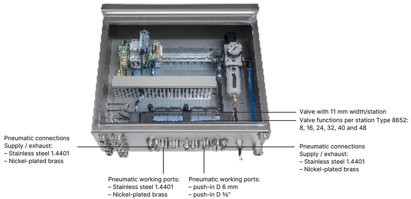
| Component | Material / Specification |
|---|---|
| AirLINE Quick Adapter Plate | Stainless steel 1.4301 (304) |
| Supply / Exhaust Ports | Push-in connector D10 mm, stainless steel 1.4401 (316) |
| Pneumatic Working Ports | Push-in connector D6 mm, stainless steel 1.4401 (316) |
| Mounting Fasteners | Screw set M5 × 10 A2 DIN 6912 |
| Enclosure Rating Achievement | IP65 / NEMA 4X (closed cabinet installation) |
The 16-slot valve block without intermediate supply exhibits a length of A = 99 mm and B = 198 mm, fixed by 10 x M5 mounting screws.
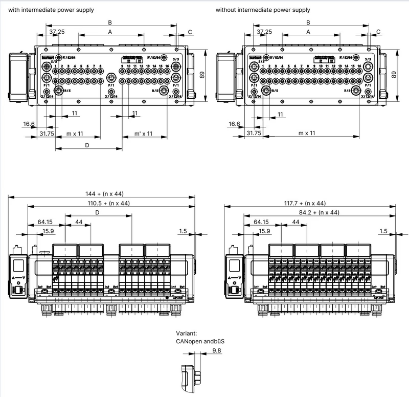
| Variant Configuration | A [mm] | B [mm] | C [Screws] | D [mm] | m | m' | n |
|---|---|---|---|---|---|---|---|
| 16-fold without intermediate feed | 99 | 198 | 10 x M5 | — | 15 | — | 4 |
| 16-fold with intermediate feed | 112 | 224 | 10 x M5 | 114.3 | 7 | 7 | 4 |
| 20-fold without intermediate feed | 121 | 242 | 10 x M5 | — | 19 | — | 5 |
| 20-fold with intermediate feed | 134 | 268 | 10 x M5 | 158.3 | 11 | 7 | 5 |
| 24-fold without intermediate feed | 143 | 286 | 10 x M5 | — | 23 | — | 6 |
| 24-fold with intermediate feed | 156 | 312 | 10 x M5 | 158.3 | 11 | 11 | 6 |
Hot Swap Maintenance Spacing
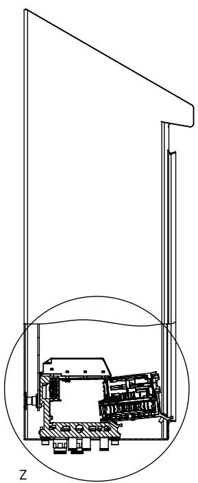
To enable the Hot Swap function, observe minimum clearance distances between the valve terminal and the control cabinet door or wall. Valves can be replaced under pressure without interrupting the operation of adjacent valve slices.
The terminal interface separates the electronics/communication power supply from the pneumatic valve coil power supply. This ensures that an emergency shutdown of the pneumatic actuators does not drop network communication or sensor feedback.
| Pin / Terminal | Wire Colour | Assignment | Notes |
|---|---|---|---|
| 1 | Red | +24 V DC | Main electronics power supply |
| 2 | White | CAN_H | büS communication line |
| 3 | Green | SHIELDING | Cable shield connection |
| 4 | Blue | CAN_L | büS communication line |
| 5 | Black | GND (0 V DC) | Power and bus reference ground |
| Terminal | Wire Colour | Assignment | Notes |
|---|---|---|---|
| 1 | Red | AUX +24 V DC | Solenoid valve coil supply |
| 2 | Black | GND (0 V DC) | Solenoid valve coil ground |
Dual RJ45 Ethernet ports allow linear line and ring topologies across PROFINET IO, EtherNet/IP, Modbus TCP, EtherCAT, and CC-Link IE Field Basic:
| Pin | Signal | Assignment |
|---|---|---|
| 1 | TX+ | Transmit Data + |
| 2 | TX- | Transmit Data - |
| 3 | RX+ | Receive Data + |
| 4 | N.C. | Not connected |
| 5 | N.C. | Not connected |
| 6 | RX- | Receive Data - |
| 7 | N.C. | Not connected |
| 8 | N.C. | Not connected |
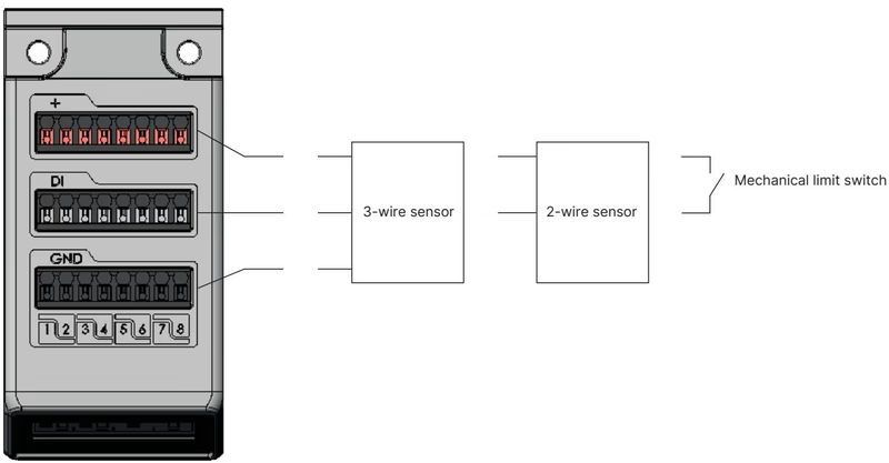
BURKERT 20014860 includes four 8DI electronic modules, providing 32 digital input channels. Each module provides 24 V DC sensor power with a maximum current limit of 30 mA per digital input.
| Parameter | Technical Value |
|---|---|
| Compatible Sensors | 2-wire sensors (10–30 V), 3-wire sensors, mechanical limit switches |
| Switching Thresholds | $V_{\text{OFF}} = 0\dots5\text{ V}$, $V_{\text{ON}} = 10\dots30\text{ V}$ |
| Input Current at $V_{\text{ON}}$ | Max. 5.7 mA per channel (typical at 24 V DC) |
| Input Impedance | > 4 kΩ |
| Galvanic Isolation | None (common reference potential across all channels) |
| Diagnostics Capability | Open-circuit detection with 2-wire sensors, short-circuit detection with 3-wire sensors |
| Maximum Cable Length | < 30 m |
| Wire Cross-Section | Pluggable spring terminals, $0.14\dots1.5\text{ mm}^2$ (AWG 28–16) |
| Sensor Type Used | Sensor Actuated | Sensor Not Actuated | Short Circuit | Wire Break |
|---|---|---|---|---|
| 3-Wire Sensor | Yes | Yes | Detected | — |
| 2-Wire Sensor | Yes | Yes | — | Detected |
| Mechanical Limit Switch | Yes | Yes | — | — |
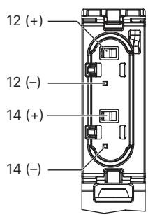
Position 1 is fitted with a Type 6534 SIA valve, allowing a safety circuit to interrupt the power supply of that specific valve station independently of the fieldbus controller.
| Feature | SIA Technical Detail |
|---|---|
| Electrical Connection | Pluggable, coded 2-pin screw-type terminal, wire cross-section $0.14\dots1.5\text{ mm}^2$ |
| Switching Capacity | 0.5 A at 24 V DC |
| Override Handling | SIA valves omit manual override levers to prevent inadvertent bypass |
| Commissioning Delivery State | Terminals supplied with a bridging jumper; jumper must be removed before field wiring |
| Switching State (Unpowered) | Normally closed (CF-C) |
Safety Interlock Wiring
Connect the SIA connection terminals strictly to potential-free dry contacts such as emergency stop relays or mechanical safety switches. Do not apply external auxiliary voltages to the SIA contacts.
The valve terminal acts as a fieldbus gateway head in modular process architectures. It links the master controller over Industrial Ethernet and branches via büS (CANopen-based Bürkert system bus) to subordinate pneumatic islands, valve positioners, or field transmitters.
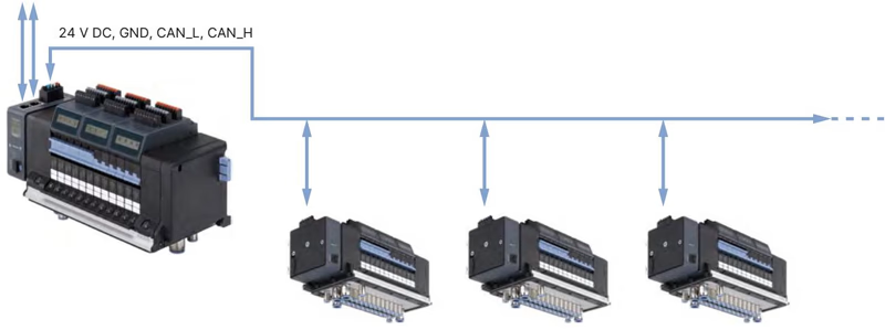
Parameter configuration, firmware updates, cyclic process data mapping, and diagnostic recording are managed using the Bürkert Communicator software (Type 8920) via a PC-connected USB-büS interface set (article no. 772426).
When installed within an appropriate secondary enclosure, Type 8652 valve islands comply with international explosion protection standards:
| Standard / Certification | Ex Marking / Protection Level |
|---|---|
| ATEX (Directive 2014/34/EU) | II 3G Ex ec IIC Gc / II 3D Ex tc IIIC Dc (Certificate BVS 20 ATEX E 031 U) |
| IECEx Scheme | Ex ec IIC Gc / Ex tc IIIC Dc (Certificate IECEx BVS 20.0024 U) |
| North America (cURus HazLoc) | Class I, Zone 2, AEx ec IIC Gc / Class II, Zone 22, AEx tc IIIC Dc; Class I Div 2 Groups A,B,C,D; Class II, III Div 2 Groups F,G |
| China Compulsory Certification (CCC) | GB/T 3836 series compliance for Zone 2/22 explosive atmospheres |
Hazardous Atmosphere Restrictions
In explosive gas or dust atmospheres, the following conditions must be strictly observed:
| Article No. | Component Description |
|---|---|
| 20014860 | Complete Type 8652 AirLINE 16-slot valve island (VA AirLINE Quick, 32 DI, Industrial Ethernet) |
| 301374 | Replacement valve Type 6534, 2x 3/2-way CF-C normally closed (24 V DC, 270 l/min) |
| 338802 | Replacement valve Type 6534 SIA, 2x 3/2-way CF-C with safety shut-off port (24 V DC) |
| 335779 | Type 6534 blanking dummy plate for vacant valve slots |
| 384872 | 8DI digital input electronic module with diagnostic wire-break/short-circuit detection |
| 301799 | Fieldbus gateway Type ME43 Industrial Ethernet (PROFINET, EtherNet/IP, Modbus TCP, EtherCAT) |
| 920180 | 5-pin spring-loaded terminal plug for communication and display power supply |
| 920442 | 2-pin spring-loaded terminal plug for pneumatic valve coil power supply |
| 308661 | Mounting screw set M5 × 10 A2 DIN 6912 (10 pieces per set) |
| 772426 | USB büS interface set 1 (Type 8923) for Bürkert Communicator connection |
Explore similar products in our catalog


