

PN16

BURKERT 20031840 (Type 8652 AirLINE) is a 12-bank pneumatic valve island with Industrial Ethernet, 10x 5/2-way monostable valves, 2 blind plates, 24 DI, and aluminium AirLINE Quick base.
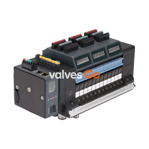
BURKERT 20031840 (Type 8652 AirLINE) is a factory-configured 12-bank modular pneumatic valve island integrating multiprotocol Industrial EtherNet communication and an aluminium AirLINE Quick interface. Equipped with ten 5/2-way monostable pneumatic pilot-controlled valves on positions 1 through 10 and two reserve blind plates on positions 11 and 12, the unit controls pneumatic actuators in automated process environments. The valve island includes 24 digital inputs arranged across three electronic modules, internal auxiliary pilot air routing, pneumatic HotSwap at port 1 (P), and integrated exhaust check valves at ports 3 (R) and 5 (S).
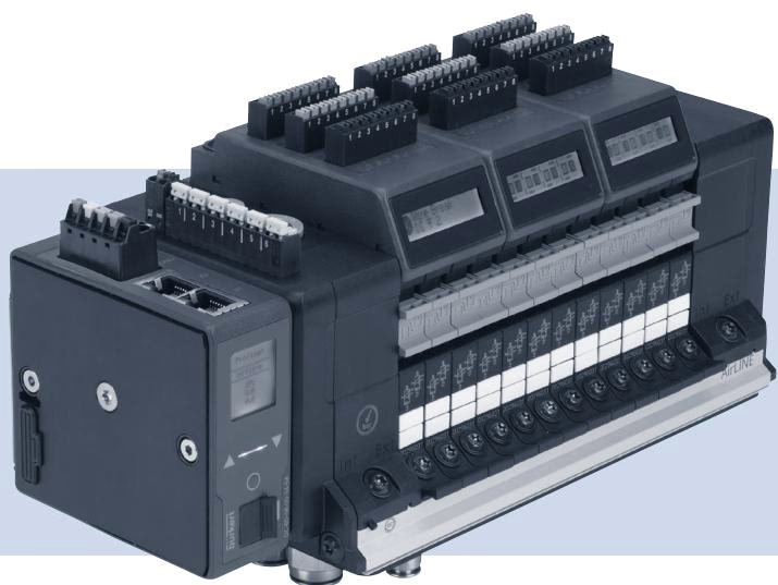
Article 20031840 is built with 12 valve positions, populated as follows:
| Position | Function / Installed Component | Details |
|---|---|---|
| Position 1 | 5/2-way monostable | Circuit function CF-H |
| Position 2 | 5/2-way monostable | Circuit function CF-H |
| Position 3 | 5/2-way monostable | Circuit function CF-H |
| Position 4 | 5/2-way monostable | Circuit function CF-H |
| Position 5 | 5/2-way monostable | Circuit function CF-H |
| Position 6 | 5/2-way monostable | Circuit function CF-H |
| Position 7 | 5/2-way monostable | Circuit function CF-H |
| Position 8 | 5/2-way monostable | Circuit function CF-H |
| Position 9 | 5/2-way monostable | Circuit function CF-H |
| Position 10 | 5/2-way monostable | Circuit function CF-H |
| Position 11 | Blind plate | Empty position for expansion |
| Position 12 | Blind plate | Empty position for expansion |
The pneumatic supply and working lines connect via push-in fittings on the aluminium AirLINE Quick base plate:
Communication and power management are concentrated in the modular fieldbus head and attached electronic modules:
According to the Type 8652 supplementary documentation for ATEX Directive 2014/34/EU and NEC standards, specific installation and operational requirements apply when installed in explosive atmospheres:
Enclosure and Electrical Installation Requirements
HotSwap Restrictions in Hazardous Atmospheres
HotSwap valve replacement under pneumatic supply pressure is strictly prohibited while an explosive atmosphere is present. Valve extraction or insertion using the HotSwap mechanism is permitted only when verified non-hazardous by calibrated atmospheric testing instruments.
Units certified for hazardous areas carry two plates: a standard technical rating plate and an Ex approval marking plate.

| Position | Description | Value / Identification |
|---|---|---|
| 1 | Device Type | Type 8652 AirLINE |
| 2 | Pressure Range | 3 to 10 bar |
| 3 | Ambient Temperature Range | -10 °C to +55 °C |
| 4 | Rated Voltage / Current Consumption | 24 V DC / 3 A |
| 5 | Serial Number | Factory designated (S/N) |
| 6 | Manufacturing Code | Factory encoded (e.g. W14AL) |
| 7 | Device Order Number | 20031840 |


| Designation | Certification Code / Data |
|---|---|
| ATEX Certificate | BVS 20 ATEX E 031 U |
| ATEX Gas / Dust Marking | II 3G Ex ec IIC Gc / II 3D Ex tc IIIC Dc |
| IECEx Certificate | IECEx BVS 20.0024 U |
| IECEx Marking | Ex ec IIC Gc / Ex tc IIIC Dc |
| CCC Compliance | GB/T 3836.2021 (certified via SITIIAS) |
| Production Monitoring | PTB (CE0102) |
| Supplementary Warning Label | WARNING DO NOT CONNECT OR DISCONNECT WHEN ENERGIZED |
Explore similar products in our catalog


