Up to 99.8% Efficiency

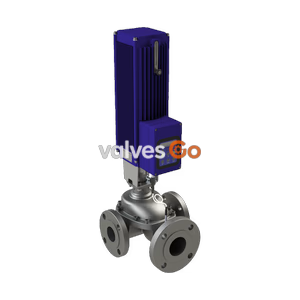
BURKERT 20045572 Type 2301 is a pneumatically operated 2-way globe control valve with DN 10 PN 25 flange connection, stainless steel seat seal, Kv 1.25 m3/h, normally closed (NC) function, and equal percentage trim.
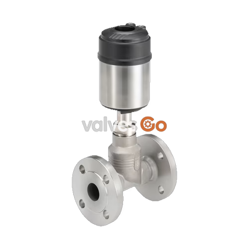
BURKERT 20045572 (Type 2301) is a pneumatically operated 2-way globe control valve engineered for continuous flow regulation of liquids, gases, and steam in industrial and hygienic process environments. Configured as a complete valve assembly under article number 20045572, the unit features a DN 10 flanged connection to DIN EN 1092-1 PN 25, a 15 mm body nominal size, and a 6 mm nominal seat orifice yielding a Kv value of 1.25 m³/h with an equal percentage flow characteristic. Operating under Control Function A (normally closed by spring force), the valve directs process medium below the seat, preventing water hammer and delivering stable throttling control across operating pressures from 0.00 to 16.00 bar(g) and fluid temperatures from -10 °C to +185 °C.
Constructed with a cast stainless steel 316L / CF3M body, a parabolic stainless steel control cone (1.4571), and a self-adjusting spindle packing gland with spring-compensated PTFE V-rings, the assembly is certified food-contact compliant according to EC Regulation 1935/2004 and FDA declarations. The valve integrates directly with ELEMENT series digital electropneumatic positioners and process controllers via internal air routing, eliminating external pilot tubing.
| Specification Parameter | Technical Value |
|---|---|
| Burkert Model & Article | Type 2301 / Article No. 20045572 |
| Port Connection Type / Size | Flange DIN EN 1092-1 / DN 10 (Pipe O.D. matching 15 mm body cast) |
| Flange Pressure Rating | PN 25 |
| Nominal Seat Diameter (Orifice) | 6 mm |
| Flow Capacity (Kv, Water) | 1.25 m³/h |
| Control Characteristic | Equal percentage, theoretical rangeability 50:1 |
| Control Function | Control Function A (CF A, normally closed by spring force) |
| Medium Flow Direction | Below seat (flow to open) |
| Medium Pressure Rating | 0.00 to 16.00 bar(g) |
| Pilot Pressure Range | 5.5 to 7.0 bar(g) |
| Medium Temperature Range | -10 °C to +185 °C |
| Ambient Temperature Range | -10 °C to +100 °C (actuator limit) |
| Valve Body Material | Stainless steel 316L / CF3M |
| Seat Seal Material | Stainless steel 1.4571 (metal-to-metal, Leakage Class IV / III) |
| Spindle Packing System | Filled PTFE V-rings with live spring compensation |
| Actuator Size & Material | 70 mm (Size M) / PPS cover with stainless steel 1.4561 casing |
| Pilot Air Interface | ELEMENT interface, 6 mm push-in connector |
| Hygienic Conformity | EC Regulation 1935/2004, FDA compliant wetted materials |
| Cleaning Capability | CIP and SIP steam sterilisation capable |
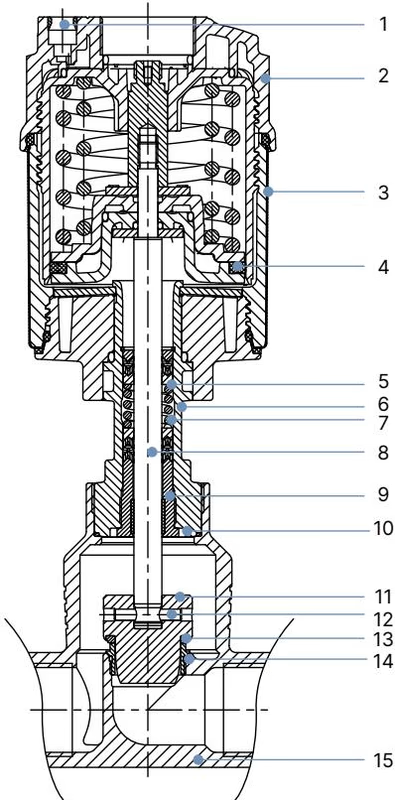
Type 2301 utilizes an angle-seat-style flow geometry inside a globe body profile, optimizing fluid flow and reducing turbulence. The parabolic control cone translates linearly through a precision spindle guide, modulating the opening area between the cone and the screw-in valve seat. The seat is threaded into the body, allowing replacement or resizing between trim sizes.
Under Control Function A, internal mechanical springs force the spindle downwards, pressing the metallic control cone into the valve seat to maintain a closed state in the absence of control air. When pilot pressure (5.5 to 7.0 bar) is admitted to pilot air port 1, it acts on the actuator piston seal, lifting the spindle against the spring package to open the flow path.
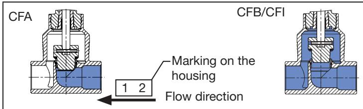
The flow direction is strictly below the seat. Medium pressure acts beneath the cone, which assists valve opening, avoids dynamic slamming during closure, and provides smooth, reproducible positioning across the stroke range.
| Item No. | Component Part | Material Description |
|---|---|---|
| 1 | Pilot air ports | Push-in connector PP (polypropylene) |
| 2 | Actuator cover | PPS (polyphenylene sulphide) |
| 3 | Actuator casing | Stainless steel 1.4561 (316Ti) |
| 4 | Piston seal | FKM |
| 5 | Springs | Stainless steel 1.4310 |
| 6 | Pipe | Stainless steel CF3M |
| 7 | Packing gland | PTFE V-rings (filled), with spring compensation |
| 8 | Spindle | Stainless steel 1.4401 (316) / 1.4404 (316L) |
| 9 | Spindle guide | Stainless steel 1.4404 (316L), PTFE filled |
| 10 | Body seal | Graphite or PTFE |
| 11 | Control cone | Stainless steel 1.4571 (optionally hardened) |
| 12 | Spring straight pin | Stainless steel 1.4310 |
| 13 | Seat seal | Stainless steel 1.4571 |
| 14 | Valve seat with O-ring | Stainless steel 1.4571 / EPDM |
| 15 | Valve body | Stainless steel 316L / CF3M |
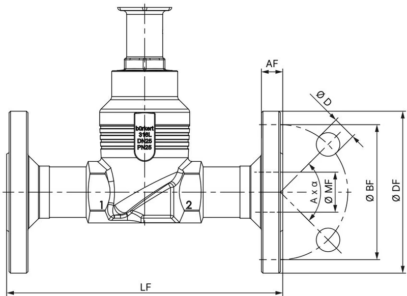
Model 20045572 incorporates a DIN EN 1092-1 PN 25 flange interface with a face-to-face length according to DIN EN 558-1 FTF 1. The dimensions in millimetres are detailed below:
| Nominal Diameter DN | Flange ∅ DF [mm] | Face-to-Face Length LF [mm] | Bolt Circle ∅ BF [mm] | Flange Thickness AF [mm] | Hole ∅ D [mm] | Bolt Quantity & Angle (A x α) | Pipe ∅ MF [mm] |
|---|---|---|---|---|---|---|---|
| DN 10 | 90 | 130 | 60 | 16 | 14 | 4 × 90° | 13.6 |
| DN 15 | 95 | 130 | 65 | 16 | 14 | 4 × 90° | 18.1 |
| Port Connection DN | Actuator Size ∅ | Actuator Outer ∅ A [mm] | Total Height H [mm] | Overall Height with 8692 / 8693 [mm] | Overall Height with 8694 / 8696 [mm] | Overall Height with 8792 / 8793 [mm] |
|---|---|---|---|---|---|---|
| DN 10 | 70 (Size M) | 91 | 239 | 383 | 342 | 342 |
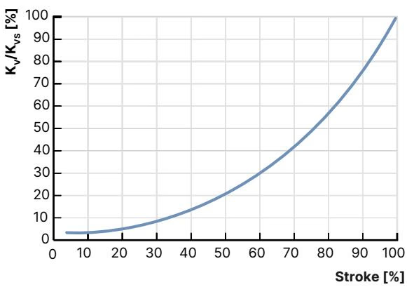
The parabolic contour of the 6 mm stainless steel control cone provides an equal percentage characteristic in accordance with DIN EN 60534-2-4 with a 50:1 theoretical rangeability. Actuator size 70 mm provides enhanced positioning control compared to 50 mm actuators, maintaining tight linearity tolerances down to 10% of stroke.
| Seat Size [mm] | Stroke 5% | Stroke 10% | Stroke 20% | Stroke 30% | Stroke 40% | Stroke 50% | Stroke 60% | Stroke 70% | Stroke 80% | Stroke 90% | Stroke 100% (Kvs) |
|---|---|---|---|---|---|---|---|---|---|---|---|
| 6 mm | 0.019 m³/h | 0.026 m³/h | 0.046 m³/h | 0.072 m³/h | 0.11 m³/h | 0.17 m³/h | 0.25 m³/h | 0.39 m³/h | 0.57 m³/h | 0.85 m³/h | 1.25 m³/h |
| Medium Temperature | Permissible Working Pressure (PN 25 Rating) |
|---|---|
| -10 °C to +50 °C | 25.0 bar |
| +100 °C | 24.5 bar |
| +150 °C | 22.4 bar |
| +185 °C (Model 20045572 Max Limit) | ~21.0 bar (Catalog max set to 16.0 bar) |
| +200 °C | 20.3 bar |
| +230 °C | 19.0 bar |
Hygiene and Food Standards
Model 20045572 wetted parts comply with European Regulation (EC) 1935/2004 and the United States Food and Drug Administration (FDA) Code of Federal Regulations according to manufacturer declarations. The unit supports clean-in-place (CIP) protocols and steam-in-place (SIP) sterilisation cycles up to +185 °C.
Type 2301 forms the Continuous ELEMENT valve system (Type 8802-GD) when paired directly with Burkert digital positioners and process controllers:
Pneumatic control channels route internally through the ELEMENT stem interface, protecting electrical contacts and pilot seals from external chemical exposure.
Safety Instructions
Commissioning and Maintenance
Explore similar products in our catalog