Up to 99.8% Efficiency

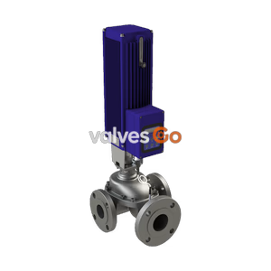
BURKERT 20045709 Type 2301 is a pneumatic globe control valve actuator for DN 15 bodies with 8 mm seat, normally closed function A, 0-16 bar operating pressure, and stainless steel trim.
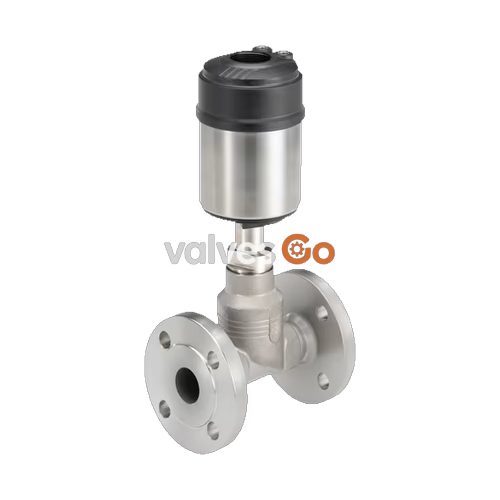
BURKERT 20045709 Type 2301 is a pneumatically operated globe control valve actuator designed for integration with DN 15 valve bodies featuring an 8 mm orifice seat diameter. Operating under control function A (normally closed by spring force), this unit regulates liquid, gas, and steam media with flow direction below the seat. The assembly incorporates a polyphenylene sulphide (PPS) actuator cover, stainless steel 1.4561 casing, self-adjusting PTFE V-ring spindle packing, and a stainless steel parabolic control cone providing an equal-percentage flow characteristic. Engineered for process environments, item 20045709 delivers tight process control across an operating pressure range of 0 to 16 bar and medium temperatures from -10 °C to +185 °C. The unit features integrated ELEMENT pilot air connections (6 mm) and complies with FDA and EC Regulation 1935/2004 food contact declarations, supporting both CIP and SIP steam sterilisation cycles.
| Specification Parameter | Technical Value |
|---|---|
| Article Number (SKU) | 20045709 |
| Valve Type Family | 2301 Continuous ELEMENT |
| Construction Type | Actuator assembly with control cone for globe control valve |
| Body Nominal Diameter (DN) | 15 mm (NPS 1/2) |
| Nominal Seat Orifice | 8 mm |
| Control Function | Control function A (normally closed by spring force) |
| Flow Direction | Flow below seat (flow to open) |
| Operating Medium Pressure | 0...16 bar(g) |
| Pilot Pressure Range | 5.5...7 bar(g) |
| Medium Temperature Range | -10 °C...+185 °C |
| Ambient Temperature Range | -10 °C...+100 °C |
| Seat Seal Material | Stainless steel 1.4571 |
| Control Cone Material | Stainless steel 1.4571 (equal-percentage profile) |
| Flow Capacity ($K_{vs}$) | 2.1 m³/h |
| Theoretical Rangeability | 50:1 |
| Seat Leakage Class | Leakage class IV according to DIN EN 60534-4:2006 |
| Control Air Connection | Interface ELEMENT (6 mm diameter) |
| Pilot Medium | Instrument air according to DIN ISO 8573-1 (Class 3 water, Class 5 oil/dust) |
| Degree of Protection | IP65 / IP67 |
| Cleaning Compatibility | CIP capable, SIP steam sterilisation capable |
| Hygienic Declarations | EC Regulation 1935/2004 and FDA compliant wetted materials |
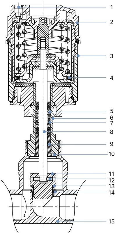
The Type 2301 ELEMENT design uses corrosion-resistant materials throughout the actuator, spindle guide, and wetted components:
| Item No. | Component Element | Material Specification |
|---|---|---|
| 1 | Pilot air ports | Push-in connector PP |
| 2 | Actuator cover | PPS (Polyphenylene sulphide) |
| 3 | Actuator casing | Stainless steel 1.4561 (316Ti) |
| 4 | Piston seal | FKM |
| 5 | Spring | Stainless steel 1.4310 |
| 6 | Pipe | Stainless steel CF3M |
| 7 | Packing gland | PTFE V-rings (filled), with spring compensation |
| 8 | Spindle | Stainless steel 1.4401 (316) / 1.4404 (316L) |
| 9 | Spindle guide | Stainless steel 1.4404 (316L), PTFE filled |
| 10 | Body seal | Graphite or PTFE |
| 11 | Control cone | Stainless steel 1.4571 (optionally hardened) |
| 12 | Spring straight pin | Stainless steel 1.4310 |
| 13 | Seat seal | Stainless steel 1.4571 (leakage class IV) |
| 14 | Valve seat with O-ring | Stainless steel 1.4571, EPDM |
| 15 | Valve body | Stainless steel 316L / CF3M |

The parabolic trim geometry provides an equal-percentage flow characteristic according to DIN EN 60534-2-4 with a theoretical rangeability of 50:1. The $K_{vR}$ value is defined at 10% stroke for seat diameters ≤ 10 mm.
For article 20045709 (DN 15 body with seat size 8 mm), the water flow capacity across the stroke range is calibrated as follows:
| Stroke (%) | $K_v$ Value Water (m³/h) |
|---|---|
| 5% | 0.070 |
| 10% | 0.080 |
| 20% | 0.11 |
| 30% | 0.13 |
| 40% | 0.19 |
| 50% | 0.27 |
| 60% | 0.43 |
| 70% | 0.63 |
| 80% | 0.95 |
| 90% | 1.6 |
| 100% ($K_{vs}$) | 2.1 |
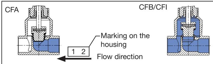
Flow Direction
The medium flow is directed strictly below the valve seat (flow to open). In control function A, the valve closes against the medium flow via internal actuator springs. The medium pressure below the control cone assists opening when pilot air is admitted.
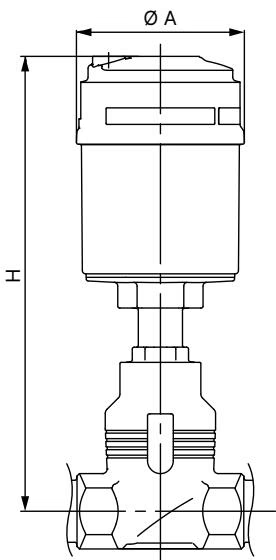
The Type 2301 globe control valve system dimensions for DN 15 process bodies depend on the selected actuator diameter and integrated automation head:
| Nominal Diameter DN | Actuator Size ∅ | Actuator Diameter ∅ A (mm) | Base Actuator Height H (mm) | Height with Type 8692 / 8693 (mm) | Height with Type 8694 / 8696 (mm) | Height with Type 8792 / 8793 (mm) |
|---|---|---|---|---|---|---|
| DN 15 (NPS 1/2) | 50 mm (D) | 64.5 | 226 | — | 329 | — |
| DN 15 (NPS 1/2) | 70 mm (M) | 91.0 | 239 | 383 | 342 | 342 |
Supported body connection standards across the Type 2301 family include:
Type 2301 combines directly with Bürkert positioners and process controllers to form the Continuous ELEMENT Type 8802-GD control system without external pneumatic tubing:
| Connection Interface | Fastener / Fitting | Tightening Torque |
|---|---|---|
| Valve body to actuator nipple (DN 10 / DN 15) | Open-end wrench flat | 45 ± 3 Nm |
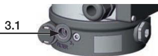
| Control unit lateral fastening screws | Hexagon socket screws (2x) | Max. 1.5 Nm |
Prevent Seal and Trim Damage
When installing, disassembling, or rotating the actuator on the valve body, the valve must always be held in the open position. For control function A, apply 5 bar compressed air to pilot port 1 before loosening or tightening the body connection.
The actuator housing can be rotated continuously through 360° to align pneumatic ports. Counterhold the wrench flat on the nipple and turn the actuator counterclockwise (viewed from below) using an open-end wrench on the hexagon head. Never use a pipe wrench.
Pressure Hazard
Before loosening process lines or removing the valve actuator, completely depressurise and drain or vent all connected piping systems. The actuator contains a preloaded internal spring; never attempt to open the actuator housing.
When supplied with variable code PX51, Type 2301 devices comply with ATEX/IECEx Category 2 equipment standards for Zones 1/21 and 2/22 (EPS 18 ATEX 2 008 X / IECEx EPS 18.0007 X: Ex h IIC T4...T2 Gb / Ex h IIIC T135 °C...T300 °C Db):
Explore similar products in our catalog